JVC Proprietary 7-pin Y/C 358 S-Video Connector
This model JVC uses a special discontinued connector style called Y/C 358. It is a half-inch diameter military-style 7-pin connector. At this time I do not know of any off-the-shelf connector that would fit this plug but here is the pinout if you want to try making your own adapter:
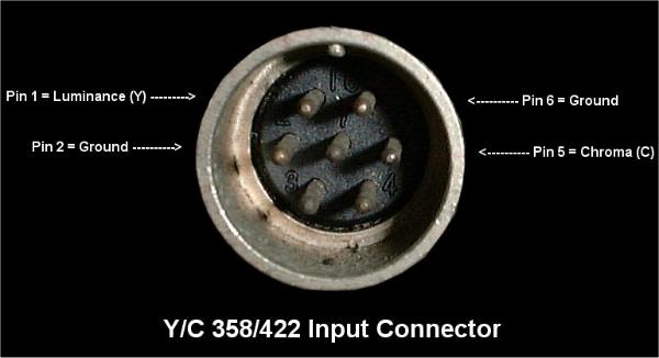
Source: Barry's 8-Track Repair
Random fact: The diameter of the holes drilled for Y/V 358 is exactly the same as the panel mount S-Video plugs you can harvest from dead PVM input boards. All you need to do is shave out the keyway on the empty hole left behind from the Y/C 358 connector so that it is a complete circle all the way around.
Here is a quick guide on how to change the wiring of a YC 358 PCB footprint to accommodate a standard s-video plug in its place:

First you need to desolder every single input plug so that you can separate the input PCB from the plastic. This is necessary in order to remove the Y/C 358 plug. Once you've done that, install the S-Video plug and put the PCB back in place. Resolder all of the inputs and continue. Cut the trace from pin 5 of the plug. This is because pin 5 of a normal S-video plug is GND, and you don't want that tied to signal input on the JVC board. Next you need to run a wire from pin 4 to the trace you cut (white wire in the above image) to carry the chroma signal, and bridge pin 3 to pin 7 (I used a leg clipping) to carry luma. Pin 2 and pin 6 can remain connected as-is.
The panel-mount S-Video ports from PVM input boards are an exact fit for the mounting on this JVC, you just need to shave off the keying on the plastic so that the hole left over is a perfect circle all the way around