RGB Mod
Written by stabarz. Source
This model, along with numerous other Sony chassis BA-1 models from the early 90s, uses a separate little S board for the closed caption decoder circuit. The header for this board has pins for R, G, B, and Ys, which connect directly to the analog RGB input pins on the CXA1465AS jungle chip. The header also has pins for 5V and ground that you can tap into.
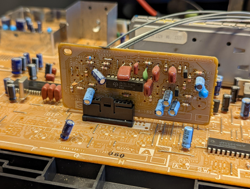
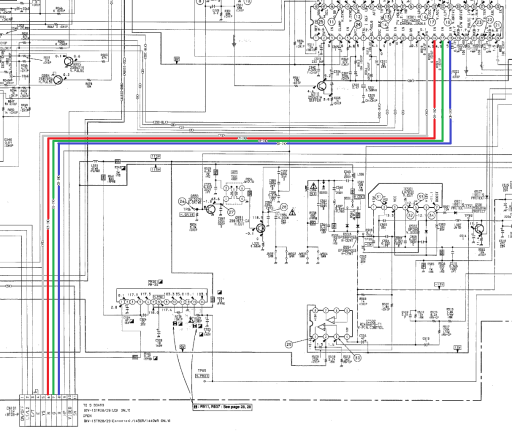
Signal path of the analog R, G, B, and Ys pins from header CN101. They connect directly to jungle chip pins 15-18.
The OSD chip is connected to the jungle chip via a separate set of digital RGB pins (9-12), so an external analog RGB signal can be inserted directly into the analog RGB pins with no need for an OSD Mux circuit.
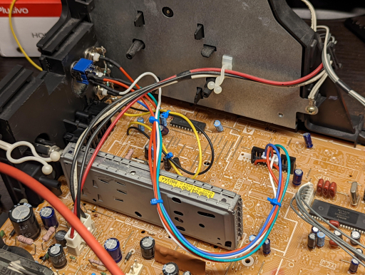
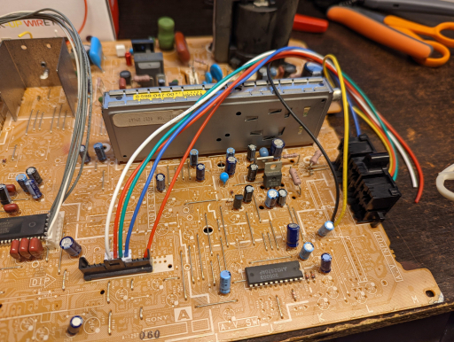
Signals wired to the A board.
I wired a 4-pin connector for the Ys, R, G, and B signals to connect to pins 5, 6, 7, and 8, respectively, on CN101. I soldered a wire for 5V because my connectors wouldn't fit right for that last pin.
The yellow wire is for sync and is connected directly to the Video 1 composite input. The black wire is ground. There is a vacant spot for connector CN402, so I soldered to the points labeled "V1 V-IN" and "E".
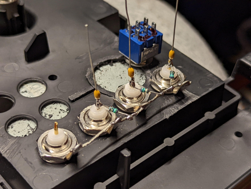
BNC connectors & switch mounted to the input panel. The input panel is a separate piece from the back cover on this model, which makes things a bit more convenient. The plastic was raised around where that one big hole is, so I had to do some cutting to make a little more room.
Added 75 ohm termination resistors to ground & 0.1uF filter caps inline for the R, G, and B connectors. No need for these on the sync line since it will be connected directly to the composite video input, which already has these.
The switch sends 5V to the Ys pin through a 1k resistor. This is what "turns on" RGB mode.
All wired & tidied up.