RGB Mod
Written by Eli Krause
Note that the stock OSD has ringing artifacts, that will hence also be present when doing an OSD mux mod.

As such, an RGB mod is not particularly recommended. But for the record, to implement it:
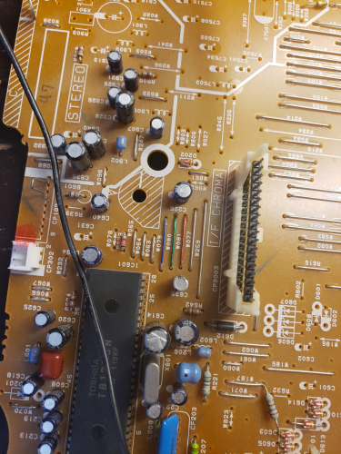
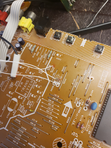
- Remove the the 1K terminating resistors R148, R149, R157
- Terminate incoming RGB lines to ground with 75 ohm resistors
- Wire incoming RGB lines through 680 ohm resistors to the following jumpers, Blue: W079, Green: W080, Red: W081

- Lift the cathode side of diode D611 to implement a blanking switch

- Wire the newly empty throughole to the center pin of an SPDT switch
- Wire the cathode end of the lifted diode to one of the two remaining pins on the switch
- Wire a 5V source, such as the throughhole of nearby empty jumper W243, through a 1k resistor to the last remaining point on the switch
- Connect all external ground lines to chassis ground
 This work is licensed under a