RGB Mod
(Credit to Mark Gaeta and MarkOZLAD for providing the instructions for the mods!)
This RGB mod is being done with a Euro-SCART connector. No switch is necessary, just change the channel to Input 1.
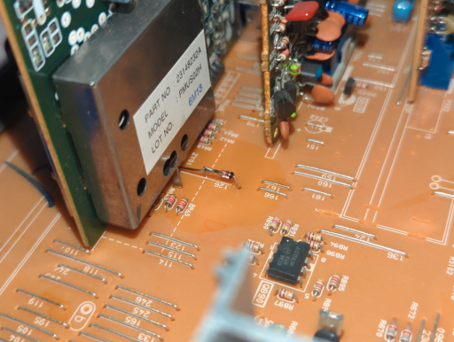
To start, lift jumper 126 and place a 1N4148 diode with the negative end facing away from the PiP board. (The SCART connector has a diode on the blanking pin to prevent voltage from going back into the connector, and that line goes through a 1k resistor, and into the cathode end of the diode placed on the board.)
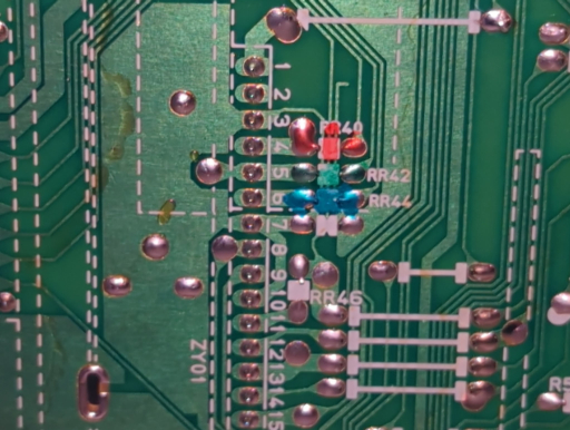
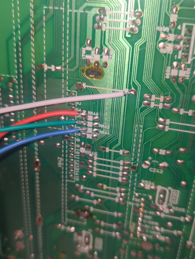
The RGB lines themselves can be placed directly on the ends of resistors RR40, RR42, and RR44 that are facing toward the PiP board. Blanking voltage is injected on the end of the lifted jumper with the diode that faces away from the PiP board:
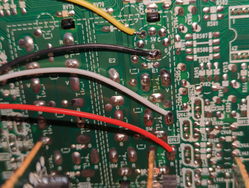
On the input board, place sync on the luma pin on the s-video connector, labeled "Y"; (no attenuation is needed for sync.) A convenient spot for ground can also be placed on the point labelled "G". As for left and right audio channels, audio goes through 1k resistors, then place the wires on the pins labeled "L" and "R".
G1 Mod
Source voltage from pin 6 of the flyback, and feed it onto the G1 board. Pin 4 on the flyback is ground. On the neckboard, cut the G1 pin and feed the negative voltage into it. Connect ground to ground.