NEC DM-2000P
December 24, 2023, 12:50 pm
August 19, 2025, 2:24 am

Summary
Literature
- I recently acquired the service manual for this and will upload a scan once I figure out the best way/place to have it scanned properly.
- Ad from Computerworld 25/07/1988
- DataSmart series pricing from Byte Magazine 10/1989
34-pin RGB Port
The 34-pin RGB input is the same pinout as Sony’s standard input, which is well documented online. You can use a floppy drive cable as the connector for the TV-side of your adapter if you choose to make one yourself like I did (see gallery below).
If you do use a floppy cable, take care to test the pins of the cable yourself using a multimeter to understand how the wires translate to the pins on the connector. The pin configuration of floppy cables is typically (but not always!) a side-by-side row pair, whereas the pin configuration of the NEC/Sony connector is two columns. This is why testing the pins and understanding their translation to the wires is extremely important for success.
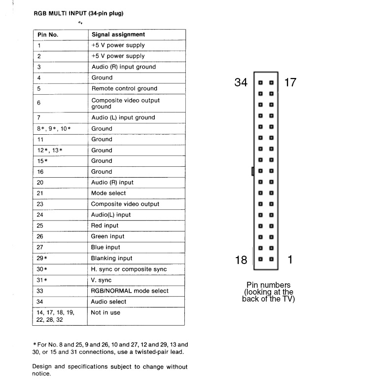
You only need to wire up the following pins shown in the table below. The floppy wire you use will be different from cable to cable so I won’t bother trying to explain that part. Just make sure that whatever wire you use is leading to the correct pin on the TV’s connector or nothing will work. CSYNC is assumed at the source, I have not tested with sync over composite video.
Note that CSYNC is fed to both the H and V sync pins even though the diagram above says H-Sync supports composite sync… I couldn’t get vertical lock on my picture without hooking up to both H and V Sync pins. I have not tested using a sync stripper to separate the CSYNC back to HV sync either.
| Signal | NEC Pin # (corresponds to chart above) | SCART Pin # |
|---|---|---|
| Ground | 6 (or any other ground) | 4, 5, 9, 13, 18 |
| Red | 25 | 7 |
| Green | 26 | 11 |
| Blue | 27 | 15 |
| Sync | 30, 31 | 20 |
| Audio L | 24 | 6 |
| Audio R | 20 | 2 |
Gallery


| Specifications | |
|---|---|
| Brand: | NEC |
| Manufacturer: | NEC |
| Model: | 2000P |
| Series: | DM |
| Viewable Size: | 20" |
| Input Signals: | VGA, Composite, S-Video, RGB, Digital RGB, VTR |
| Sync: | HV Sync, CSYNC, Sync over Composite |
| Native Resolutions: | VGA, 240p, 480i |
| Linecount: | 560 TVL |
| Horizontal Scan Range: | 35 kHz |
| Vertical Scan Range: | 87 Hz |
| Formats: | NTSC, PAL |
| Aspect: | 4:3 |
| Adjustments: | Internal Potentiometers |
| Flyback: | 47105333 |
| Tube: | NEC , E814B22 |
| Speakers: | Stereo, Amplifier |
| Application: | Professional |
| Cabinet Material: | Plastic |
| Launched: | 1989 |
| Country of Manufacture: | Japan |
| Degaussing: | Automatic on Power-on |