Summary
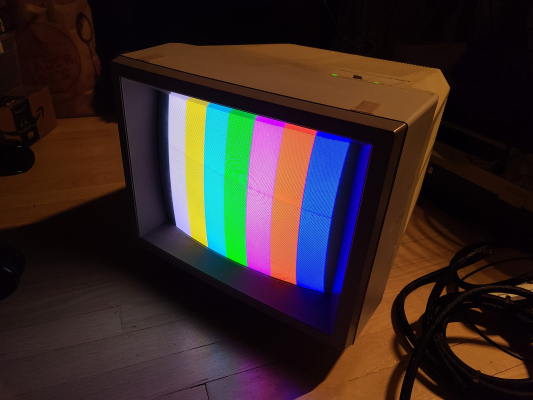
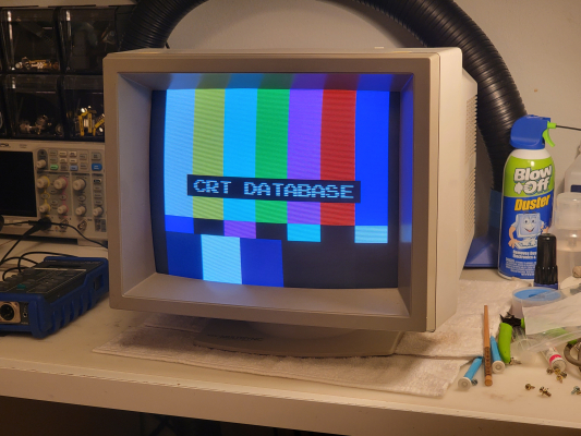
MULTISYNC HIGH RESOLUTION COLOR MONITOR
- Automatically scans all frequencies between 15.75KHz and 35KHz
- Compatible with IBM PC/AT, PC/XT, PC and look-alikes
- Compatible with all three PC color graphics boards made by IBM
- Color resolution up to maximum 800 dots horizontal, maximum 560 lines vertical is superior to any comparatively priced monitor
- Color capability limited only by the graphics card being used
- Text switch provides 7 colors for more comfortable word processing and database applications in TTL mode.
This monitor uses sync timings to determine the scan rate for the input signal. There is a list in the owner's manual of what it is guaranteed to sync to (15Khz, 22Khz, 31Khz) but in reality it can sync to anything in that range, provided the sync is clean and fits within the parameters specified.
Manuals
- Owner's Manual - coming soon, I have a physical copy on-hand
- Service Manual
Media & Promo Materials
Notes
Spare Parts
The 1401 and 1402 share the following major parts:
- Power Supply
- Yoke
- Flyback
Adjustment Procedure
Since this monitor handles multiple scan ranges, it has a fairly specific adjustment procedure in the service manual which must be followed.
The most fundamental concept that you should understand before adjusting this monitor is that it has a two-layer raster... a background raster and a foreground raster. The background determines the overall area of the tube which can display an image before the foreground raster folds at the edges, and the foreground raster is the actual picture being displayed from the signal input. The sizes of both raster layers can be adjusted independently and there is a set of 3 horizontal foreground raster size adjustments for each scan range.
The first thing you should do is make sure the background raster is centered horizontally and vertically. you can easily check this by turning the brightness up using the top adjustment panel and then using the internal potentiometers to move the background raster around until it is centered. Once you have that done, you can test a 15Khz signal to work on the foreground raster position and work your way through the higher scan ranges one at a time until you are happy with the results. You won't ever get it perfect, the monitor will always require some H-position tweaking when switching between different scan ranges.
Capacitors
Recommend immediate inspection of the power board capacitors - they are a bad brand from 1986 which is known to leak. Every single one on mine was leaking.
Sync
For RGsB (Sync on Green), the monitor will accept sync from the green video signal at the standard of 0.3-0.6vpp. For all other cases (HV Sync, CSync), it needs TTL level to pin 4 (and 5 for V Sync) of the DB9 connector.
Horizontal Output Transistor (2SC3486) Notes
This horizontal output transformer is used across all four of the multisync NEC JC-140X models. I've had to deal with several ones which are dead, so I wanted to include some notes about how to tell if yours is dead.
A "probably good" 2SC3486 will have the following measurements from a multimeter in resistance mode:
- 340-370K with red probe on base and black probe on emitter
- "OL" out-of-range with red probe on emitter and black probe on collector. If you get a reading of 50M or less resistance, the internal diode is bad, regardless of what diode check shows you. This was consistent across all 4 dead 2SC3486's I've replaced.
A "probably good" 2SC3486 will have the following measurements from a multimeter in diode-check mode:
- beep/good with black probe on collector, red probe on base
- beep/good with black probe on emitter, red probe on base.
- all other combinations of the legs should not show any voltage reading or good beeps on the multimeter.
Be careful to make sure the paper guard behind the 2SC3486 remains in place when replacing one. If the back plate of the chip makes direct metal to metal contact with the heat sink its mounted to, it will arc and kill the chip when powered.
DB9 Pinout
MultiSync                VGA
9 Pin D-sub 15 Pin Mini D-sub- Red <------------------> 1
- Green <----------------> 2
- Blue <------------------> 3
- H Sync/CSync <-------> 13
- V Sync <---------------> 14
- <-----------------------> GND
- <-----------------------> GND/NC
- <-----------------------> GND/NC
- <-----------------------> GND/NC
Videos
Gallery


 This work is licensed under a