Component & S-Video mod
Written by Matt Ross (6tanks)
The L03.2U chassis TVs, like most Philips sets from that time, used a 1-chip jungle design with integrated OSD and cannot accept an external RGB signal. However, some of these TVs can be modified to accept component and S-Video directly. Unlike some manufacturers, Philips did not use any edge enhancement or artificial sharpness filters on their component inputs, so the video quality is excellent. Thanks to user "Stonesipping" for first documenting this on the Shmups forum RGB mod thread.
This guide is applicable for some TVs with the L03.2U chassis: 14MS2331, 20MS2331, and 20MS1336. Unfortunately, mono sound TVs with this chassis, such as the 20MT1331/17, have a different firmware version that does not work with this mod. A similar procedure can be used for other Philips & Magnavox models, although the pinout for the jungle chip may be different.
On this TV, Component and S-Video inputs can be enabled by changing the option bits in the service menu. These settings determine what features are active or disabled. Use an original remote to enter the service menu by pressing "0 6 2 5 9 6 Menu". Now, select "Options" by pressing right. Cycle to OP 5 with the down button, select it by pressing right, and enter "204" using the number keys. Press "menu" to return to the service menu, power off the TV, and unplug it for at least ten seconds. This will write the changes to memory. Now, when you power on the TV, two new inputs labeled "SVHS" and "CVI" will be available. For a detailed explanation of how the option bits work, refer to page 30 of the service manual.
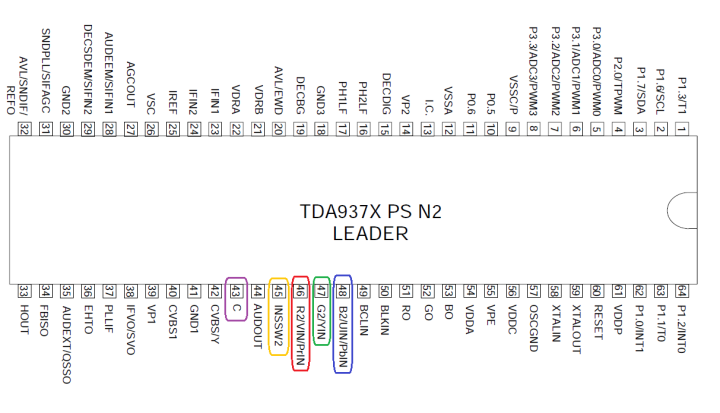
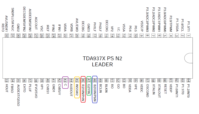
The TDA9377 jungle chip has input pins for Y, Pb, Pr, and S-Video Chroma, as well as an input select pin:
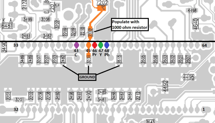
To enable component input, pin 45 of the jungle chip (INSSW2) must be connected to a +8v power supply through a 1000 ohm resistor. This can be done by populating position 3232 on the bottom of the PCB:
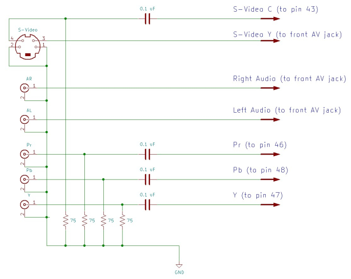
The Y, Pb, Pr, and Chroma signals each require a 75 ohm terminating resistor to ground, and an inline coupling capacitor (0.1 uF works well) before connecting to the jungle chip. S-Video Luma should be connected directly to the front composite input, with no additional components needed. The inputs can be wired as follows:
I used 26 gauge ribbon cable, attached to the bottom side of the jungle chip pins and front RCA jack:
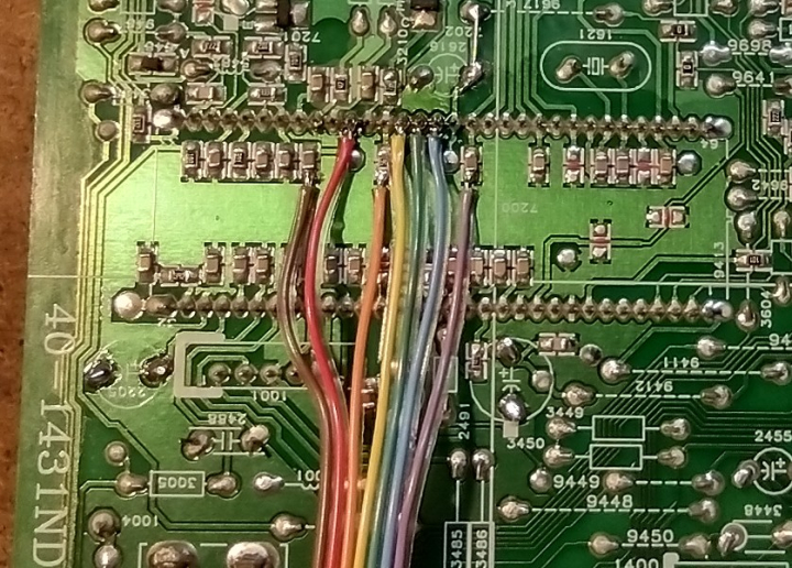
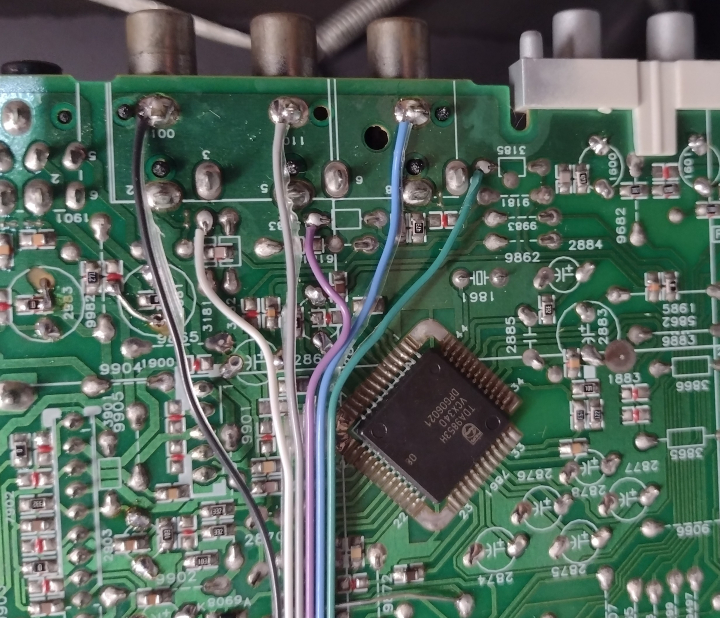
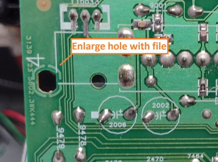
To route the wires to the top of the board, I enlarged a hole in the PCB near the tuner and ran the wires straight back from the jungle chip:
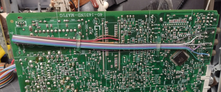
I secured the wires to the top of the PCB with a bead of hot glue, to keep them away from the RF jack. It's a good idea to use quick connects so that the back case can be easily removed:
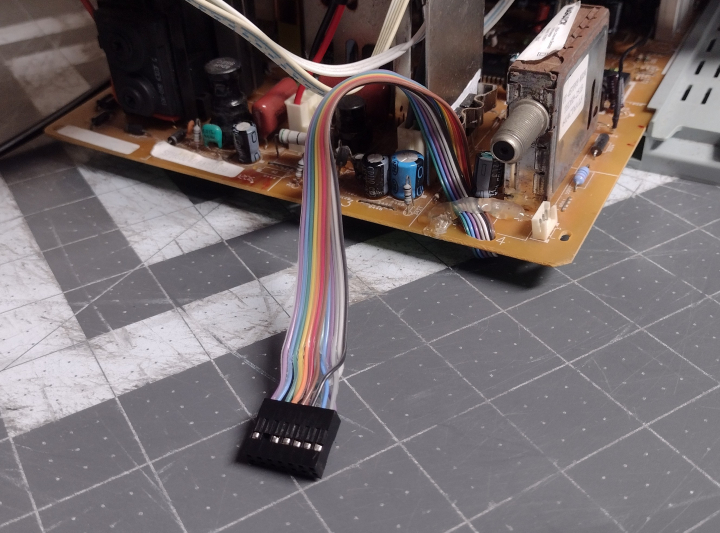
RCA jacks for YPbPr and audio and a mini DIN for S-Video were installed in the back of the case. Terminating resistors and coupling capacitors were wired directly to the input connectors:
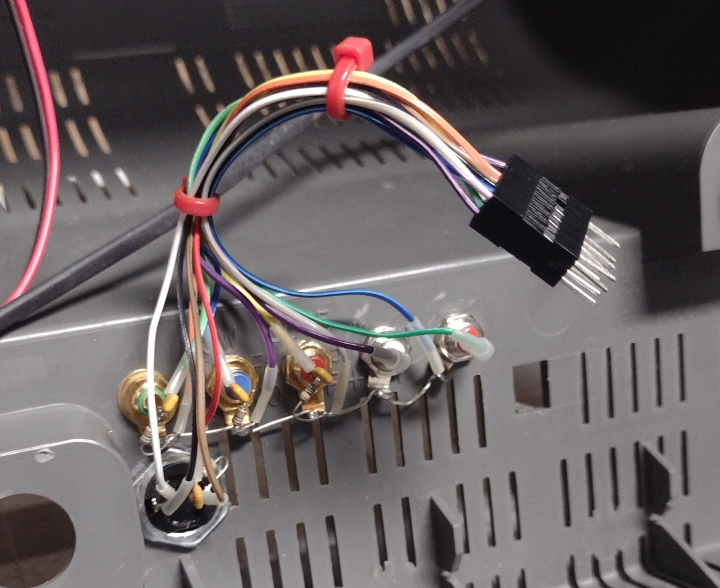
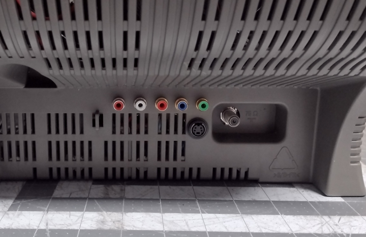
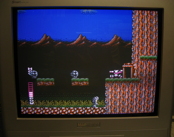
With the mod finished, the TV will display a very clean picture through component or s-video when the proper input is selected.
 This work is licensed under a