Summary
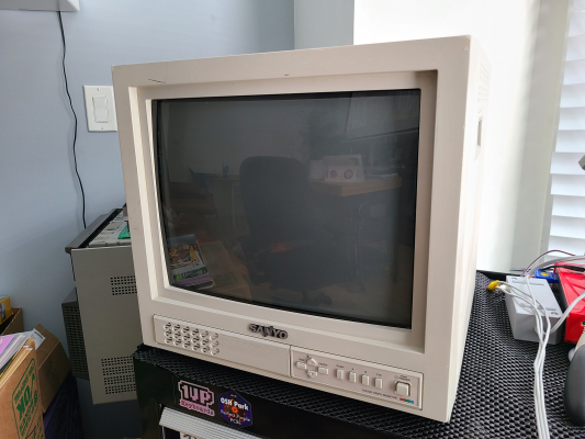
A CCTV with an excellent quality tube and comb filter. Lots of potential to be unlocked here.
There are several models of the Sanyo VMC-8xxx that have 800TVL Chunghwa tubes, availble in 14" and 19/20" models. There are other revisions of each size which have a much less impressive 400TVL tube in them, so pay attention to your model numbers!
Literature
RGB Mod (Direct) Instructions
The Sonic and Metal Slug images below are shown using the RGB input from this mod.
The Jungle chip in this CRT is already built to take RGB input so that makes our job pretty easy.
Note before you begin: There are two known revisions of the main board in this CRT chassis. The newer revision has a different jungle chip with a different pinout, *and potentially will not be RGB-moddable (see second note below)**. This guide provides references for both board revisions, the newer revision will be marked accordingly. The newer revision uses a Sanyo LA76818J jungle and the RGB input caps are C204, C205, and C206.
Second note: The newer LA76818J jungle has separate bias/contrast for the RGB inputs which cannot be changed. The values are stored in EEPROM and there is no service menu on this TV to write new values for the settings. There is a high chance that the stock values of these settings will NOT be correct for a good RGB mod. In my experience the RGB input was heavily biased to green, to the point where the background of the tube was green on a black screen. This was unfixable and I had to abandon the mod until later adding my own seperate RGB amplification + clamping which allowed me to bypass the Jungle entirely and inject my RGB signals straight into the neckboard. Before you bother trying to use the RGB inputs on the jungle I suggest testing it by just applying 3v to the blanking pin (17) and seeing what happens to the screen. If it changes colors on a black screen you are going to have the same problem as me and should just stop before you waste more of your time.
Parts List
- 3x 0.1uF film capacitors. There are some already on the board you can use but the legs need to be lifted and they are too short to work with. I just removed them and put new ones in.
- 3x 75Ohm 1/4w resistors for signal termination
- 1x 1KOhm 1/4w resistor for blanking
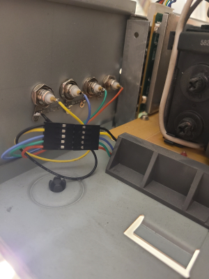
- 1x SCART connector or 4x BNC Panel Mount female connectors + 1x RCA Audio female connector. I opted to go BNC since the case is metal and a SCART socket is out of my ability to cut properly in metal. I also wanted this to be a "sleeper" mod that looks as factory as possible.
RGB Wiring
Your R G and B wires need to go through the existing 0.1uF coupling capacitors into the chroma chip (IC202 TDA8361 or IC201 LA76818J). I removed the factory film caps and replaced them with my own to get longer legs to work with, but you can do whatever you want to do. If you kep the factory caps you will still need to desolder them and put them back on the under-side of the board. You won't be able to work with them in their original top-side location.
Red is C124 (or C204 for the LA revision), Green is C123 (C205 for the LA revision), and Blue is C122 (C206 for the LA revision). Desolder the ground leg of each cap and leave it floating, this is where you will connect your R, G, and B signal wires respectively. Remember, you only want your signal running through the cap to the chroma chip. It shouldn't be tied to ground with the cap.
At some point in your signal wiring you need to terminate the RGB input signals to ground via the 75Ohm resistors you have. I chose to do it right on the board by soldering each one to the (now empty) ground side of the 0.1uF capacitor spots (C122/204, C123/205, C124/206). The other leg of the resistor will connect to the same spot your signal wires are connected, effectively tying each one to ground with 75Ohms of terminating resistance.
Once you're done, each color's wiring should look like this:
Signal wire from input -> 75ohm resistor leg -> 0.1uF capacitor -> jungle. The resistor will have it's other leg tied to ground, and the capacitor will have one leg lifted to connect to the signal/resistor, and the other leg will still be soldered to the board which will connect it to the jungle.
Drilling the holes
Thought I'd add some quick notes on how I drilled the holes, since this may be your first run-in with a metal chassis RGB Mod. You'll need to pick up some metal-compatible drill bits ($15 bucks off Amazon) and a metal hole punch. Start by marking your holes using some graph paper or other easy method. Make sure you leave enough space between each connector! Next, you will want to punch a guide hole into the metal before you drill. Metal drill bits have a tendancy to drift off, which means your holes won't be where you meant them to be.
Once you punch the hole, you can either start off with the correct size drill bit or you can start with a super small one as a pilot hole. However, remember this isn't like drilling through wood or plastic - don't slowly step up your bit size until you get to the one you want... you'll end up with the bit catching on the metal and biting it hard - which usually ends up bending the whole metal panel. The key here is to just start with the actual size drill bit you intend for your hole to be sized by. Apply lots of pressure and take breaks after about 10 seconds to make sure the bit doesn't get too hot. It shouldnt take more than a minute or two for each hole.
Sync (and Audio + Signal Ground)
While technically you could just plug your Sync BNC connector into the Line B input and be done, you will find that most BNC cables do not have the length necessary to stretch the connectors that far apart from each other. I opted to install 4 BNC female connectors for my mod so that there was a clolser option for plugging in Sync. If you are opting to install a SCART connector instead of BNC then you will obviously need to do this wiring step no matter what.
Sync needs to be fed to the Line B input pin, which is hidden on the input board behind a soldered RF shield. Don't try to take the easy route and wire your sync to P201 where the input board feeds into the main board - I tried it and this won't work because the input board amplifies the signals by 6dB and buffers them before sending them to the mainboard via that connector.
You will need to remove the input board from the chassis (2 screws, 1 on either side, careful not to drop the washers) and desolder the rear RF shield off of it - there are four legs to desoler. Applying a little bit of pressure with heat will make your job easier, but careful not to pull too hard or you will rip the traces. If one or two rip it's not the end of the world but be careful! Once you get the shield off you'll have access to the conductor side of the input board for soldering :)
Sync needs to go to BNC203's input pin, which is the center pin from the connector. You should also take this opportunity to solder a wire for signal ground if you haven't done so already elsewhere.
While you're here, wire up your audio input wire to the female RCA signal pin for Line B (RCA 705). Volume control for this CRT is found in the OSD menu, which is kind of quirky. If you don't have any sound then check your volume level! Most people in a professional setting probably had this at zero.
Blanking
This is a neat little trick I did to handle blanking - I used the switching voltage for Line B input as the blanking voltage. This effectively means that going to Line B is your RGB input button! No interferance with other inputs, even when you have something RGB connected to the monitor.
To do this you need to run a wire from pin 7 of the input board connector on the main board (P201) to the nearby jumper that leads straight into the blanking pin of the chroma chip (J206). Use a 1k resistor on either end of this wire to step down the voltage slightly, as it needs to be under 3v to activate the RGB input with OSD mixing, without doing total output blanking.
Now you're done! Hit the Line B switch on the front and watch your jaw drop at this gorgeous Chunghwa 800TVL tube display RGB in full glory.
Gallery


 This work is licensed under a