RGB Mod
Written by Matt Ross (6tanks)
Sharp TVs with the Toshiba TB1253AN jungle chip can be modified to accept RGB via the OSD circuit. These TVs have excellent component video, and RGB does not provide an increase in picture quality. However, the mod could be useful in cases where YPbPr is not available. One downside of this jungle chip is that the RGB black levels do not match the video inputs, so it's necessary to manually adjust brightness when switching video modes.
I did not finish the mod on this TV, and restored it to its original condition before modifying the case. However, I was able to verify that it works and document the process.
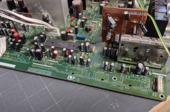
The TB1253AN chip has a set of analog RGB inputs for the OSD, and accepts standard 0.7Vpp input levels. Unlike many Toshiba jungle chips, brightness and contrast are adjustable. The chip is labeled IC 201, and is located near the edge of the TV in front of the tuner. Most of the work will be done in this section and near the AV ports.
As can be seen in the service manual, each OSD signal passes through a set of voltage dividing resistors and a 0.1uF coupling capacitor on its way to the jungle chip.
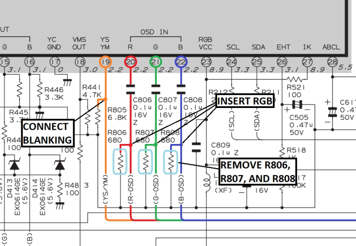
To insert our RGB signals, we need to remove the 3 resistors to ground (R806, R807, and R808), and connect RGB before they pass through the 0.1uF capacitors. Each RGB line must have a 75 ohm terminating resistor to ground and, to maintain OSD function, a 680 ohm inline resistor before connecting to the chassis.
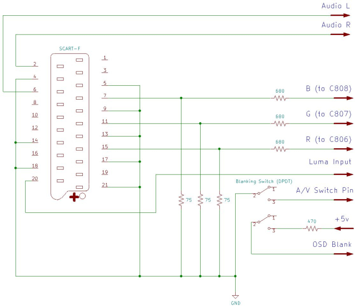
Sync (ideally in the form of composite video or luma) should be connected to the Luma pin of the S-Video input, as the comb filter used by the composite inputs will cause excessive horizontal shift in the picture. To enable the S-Video input for sync, there is a pin on the S-Video port that must be connected to ground. This can be wired in tandem with blanking if a DPDT switch is used, or hard wired if the composite input is no longer needed.
Blanking can be connected to a +5v supply via a 470 ohm resistor on one side of a double throw switch, which will provide 3.3 volts to the blanking pin. Using a higher value resistor will drop the voltage too low to blank the screen properly. I typically solder the resistor to one leg of the switch.
If using a SCART connector, wire it up as follows:
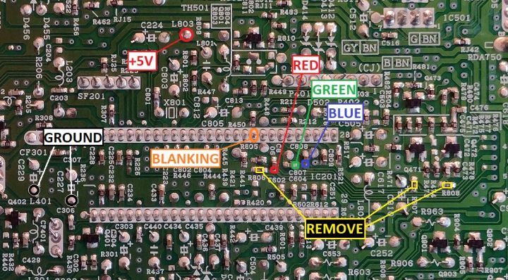
The 3 resistors that need to be removed are located on the bottom of the PCB near one end of the jungle chip. Attachment points for RGB, blanking, +5V, and ground can be found nearby.
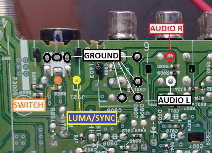
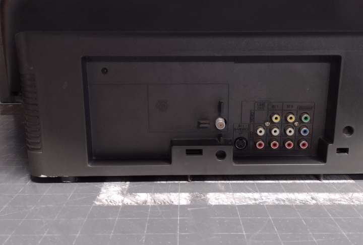
Audio signals, Sync, and the S-Video switch can be routed to the bottom of the rear AV jacks.
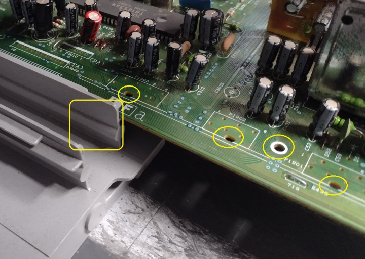
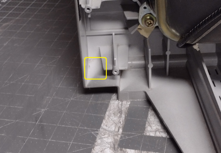
The wiring can be routed to the top of the PCB through holes located near the edge of the PCB. Alternatively, a small portion of the plastic support rail can be removed and the wires routed off the side of the board. The wiring should be directed away from the flyback transformer and the power supply section, which can cause interference. It's a good idea to add quick disconnects to the wiring so that the case can be removed without unscrewing the SCART input.
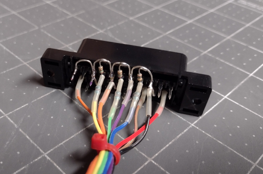
The SCART connector can be wired up with all ground pins connected together, 75 ohm termination resistors installed, and 680 ohm mux resistors inline with the RGB leads. For more information, visit the SCART installation guide.
The S-Video mode switch and blanking are connected to a DPDT toggle switch, with the 470 ohm resistor attached to the 5v line. The switch can be mounted in the left front corner of the TV for easy access.
There is plenty of space to the left of the RF tuner to mount the SCART connector. This position keeps the wiring away from the flyback transformer
Now that the mod is done, the TV will display a clean RGB image when the blanking switch is enabled and the TV is set to Video 1 input. The picture may be shifted horizontally slightly. To compensate for this, refer to pages 6 and 7 of the service manual and put the TV into service mode. Adjust D02 (Horizontal Position) until the picture is centered. If you plan to use component video as well as RGB, it may be best to set a compromise between the two since they won't line up exactly.
At this point, brightness and contrast for the RGB input will have to be adjusted in order to get a good picture. One quirk of this jungle chip is that contrast levels for RGB are only adjustable in the service menu, and are separate from the AV and component inputs. Meanwhile, RGB brightness follows the user menu settings. To do this, enter the service menu and adjust item V31 (RGB Contrast). Then, reset the TV, open the user menu, and adjust brightness to get proper black levels. This may take a few attempts to get it right, since user menu settings are reset when the TV is in service mode.
As mentioned previously, the black level of the RGB input on this jungle chip is offset from the AV inputs, and is significantly darker. As such, if brightness is properly set for RGB mode, the picture will be too bright and must be manually reduced when switching to the standard video inputs. It is possible to independently adjust brightness and contrast for component video in the service menu to match RGB, but composite and S-Video will still be off.
 This work is licensed under a