A variety of input connectors can be used when modifying a TV for RGB. These include SCART, DE-15 (VGA), BNC, and RCA jacks. Out of these, SCART is one of the most popular options for a variety of reasons. However, due to the nature of the connector it can be challenging to install properly. The method described here works well and can be done fairly quickly.
Why use SCART?
The SCART standard originated in France during the late 1970s, and has been widely used in Europe since the 1980s. The format was designed as an all-in-one connector for AV signals, and was used on a variety of devices besides TVs. Fortunately for gamers, it includes a set of RGB input pins, which allowed European TVs to display game consoles with very high quality.
SCART is especially well suited for RGB mods on NTSC televisions for two reasons. Because the standard was originally designed with consumer TVs in mind, it uses 75 ohm composite video for sync. Also, the widespread use of SCART in Europe means that cables are readily available and are suitable for use on TVs with no modifications.
With other formats such as VGA or BNC, there is a risk that the cable will carry the wrong type of sync. Many devices that output RGB, such as personal computers, some game consoles, and the MiSTer FPGA, use TTL level sync. This measures 5 volts peak to peak, which is too high for most consumer TVs. Many TVs will not sync properly with TTL sync and could be damaged by the excess voltage. An inline resistor should be added to the sync line to bring the voltage down to the proper level. Commercially available SCART cables are designed with this problem in mind, so there is less risk of ending up with an incompatible cable.
There are downsides to SCART, however. The connector itself is complicated, and the integrated audio adds extra work to wiring up the sound. Its large size and diagonal cable orientation means that selecting a site to mount the connector can be difficult. Choosing the best input connector will depend on your personal needs and the design of the TV itself.
The SCART pinout
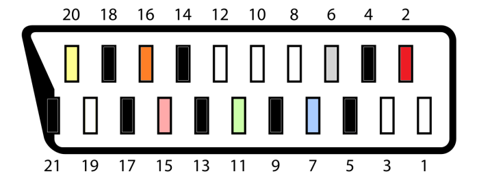
The SCART connector has 21 pins (one of these connects to the metal shield). It can be wired differently depending if it's an input or an output, and some configurations can carry S-Video. One of the pins carries a 3.3 V blanking signal, which is required by many European TVs to enable RGB. Optionally, it can also be used for auto switching in mods. For our purposes, we just need the RGB, Sync, and Audio input pins. There are eight ground pins, which should all be connected together.
Looking at the back of the TV, the pinout is a follows:
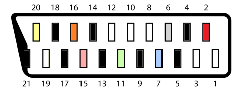
- Audio Right
- Ground
- Ground
- Audio Left
- Blue
- Ground
- Green
- Ground
- Ground
- Red
- Blanking
- Ground
- Ground
- Sync
- Ground
Preparing the SCART connector
This guide uses a panel mount female SCART connector with straight pins. It can be purchased at Console5.com.
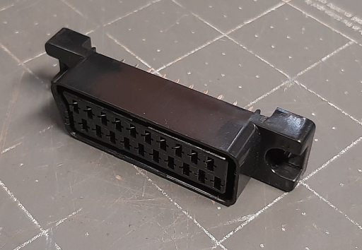
The first step is to connect the 8 ground pins together. This will help ensure a good ground for the signal, even with low quality cables that may not have all ground wires connected properly. The ground pins can be identified on the back of the connector as follows:
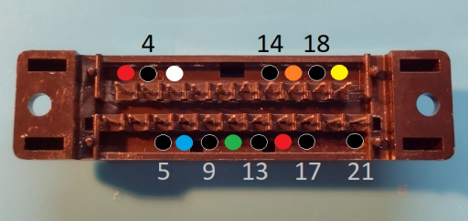
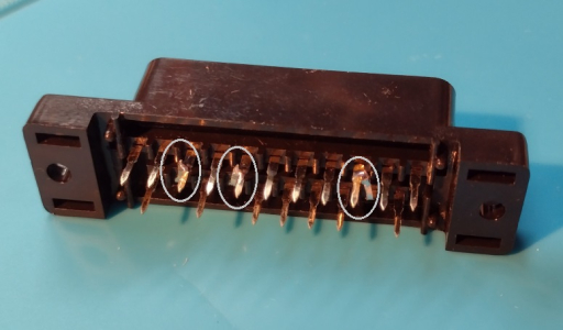
Using a set of tweezers or needle nose pliers, bend pin 4 downwards until it touches pin 5, pin 14 down to pin 13, and pin 18 down to pin 17:
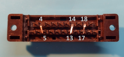
Now, turn the connector over and solder the pins together where they meet:
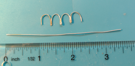
Next, cut a piece of solid core wire approximately 3.5 inches (9 cm) long. Bend it so that it forms four small arches:
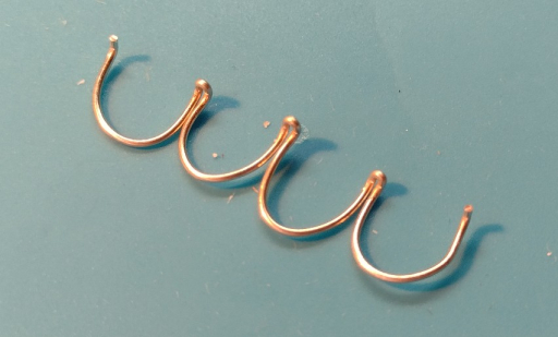
Using pliers, bend the bottom of each arch outwards to form five small "feet". Solder them to pins 5, 9, 13, 17, and 21:
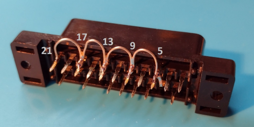
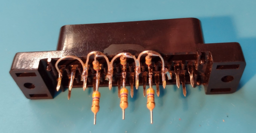
Now, the ground pins have all been successfully joined together. This structure also provides a handy place to install termination resistors.
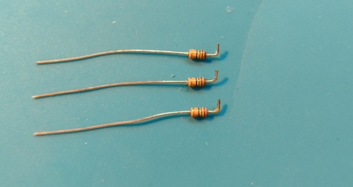
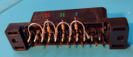
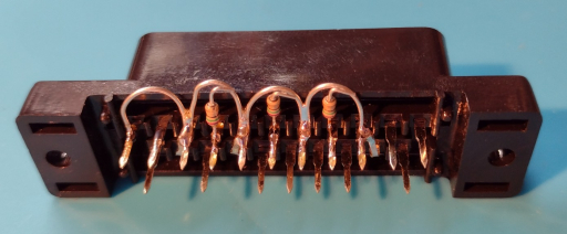
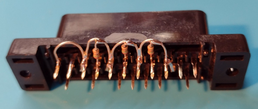
To do this, take three 75 ohm resistors, trim the ends, and bend at a right angle. These can then be soldered to RGB input pins (7, 11, and 15). Trim the tops, bend them parallel to the ground wires, and solder them in place:
Finally, components that are in line with the RGB signals such as mux resistors or coupling capacitors can be added, as the SCART connector pins provide convenient attachment points. It should be noted that placing the resistors here can lead to interference in the signal if the wires inside the TV's case are too long. If you run into this problem (and are unable to shorten the wiring), try moving these components to the chassis PCB instead.
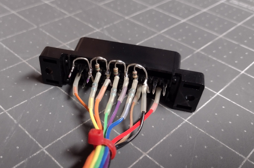
When wiring the connector to the TV's chassis, it's a good idea to use small lengths of heat shrink tubing for strain relief. Solder joints between stranded wire and the metal pins tend to be weak points, and this strengthens them considerably.
Installation
To install the SCART connector in the TV's case, I highly recommend using a SCART trim plate (also available from Console5.com). This greatly simplifies the process, as it will hide minor imperfections in the mounting hole and can be used as a cutting template. You will also need a pair of #8 x 3/4" sheet metal screws.
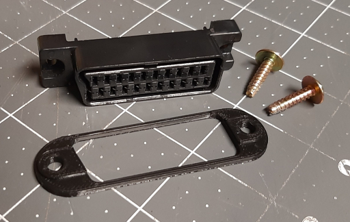
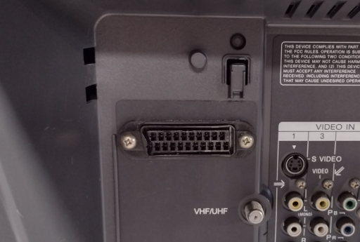
After tracing the outline of the SCART connector, I've found that the best tool for cutting the mounting hole is a Dremel tool with a 3.2 mm high speed cutter. The screw holes can be drilled with a 3/16" drill bit. The #8 screws are the right size to tap securely into the plastic of the connector without requiring any additional hardware.
When mounting the connector, pay attention to its orientation. Because SCART cables project diagonally from the plastic housing, it can get in the way if the wrong side of the connector is placed next to an obstacle.
 This work is licensed under a