RGB Mod
Written by Matt Ross (6tanks)
Sharp TVs with the SN-80 chassis can be modified to accept RGB via the OSD circuit. The TV pictured in this guide is a 13K-M100, but it should also apply to other 13" and 19" Sharp TVs with this chassis such as the 19K, 13L, and 19L models.
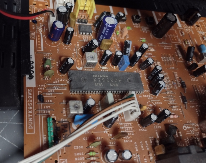
The jungle chip used is a proprietary Sharp X2933CE chip that appears to be a clone of the Toshiba TA1268N. The Toshiba version was used by a variety of consumer TVs and does have analog RGB inputs. However, the downside is that brightness and contrast levels for RGB are not adjustable from the user menu, so the picture must be adjusted via the service menu and the flyback pots once the mod is done. The jungle chip is located near the front of the TV behind the A/V jacks, and most of the work will be done in this section.
As can be seen in the service manual, each OSD signal passes through a set of voltage dividing resistors and a 0.1uF coupling capacitor on its way to the jungle chip.
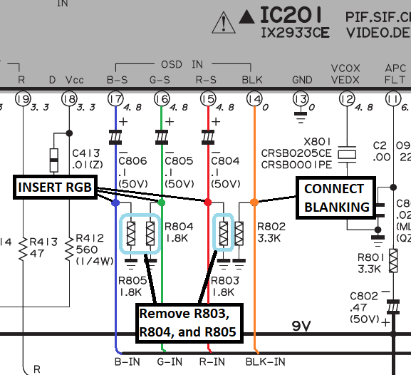
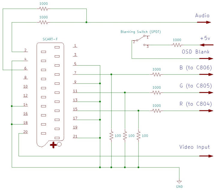
To insert our RGB signals, we need to remove the 3 resistors to ground (R803, R804, and R805), and connect RGB before they pass through the 0.1uF capacitors. Each RGB line must have a terminating resistor to ground and, to maintain OSD function, a 1000 ohm inline resistor before connecting to the chassis. In this case, due to the design of the jungle chip, using standard 75 ohm resistors will result in a picture that's too dark, so for this mod it's better to use 100 instead.
Blanking should be connected to a +5v supply through a SPDT switch, via a 1000 ohm resistor. Sync (ideally in the form of composite video or luma) is connected to the front video jack. Left and right audio are mixed using 1000 ohm resistors and routed to the front audio jack.
If using a SCART connector, wire it up as follows:
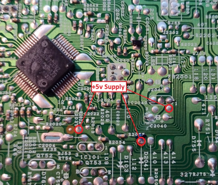
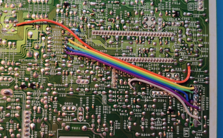
The 3 resistors that need to be removed are located near one end of the jungle chip, along with attachment points for RGB, blanking, and ground.
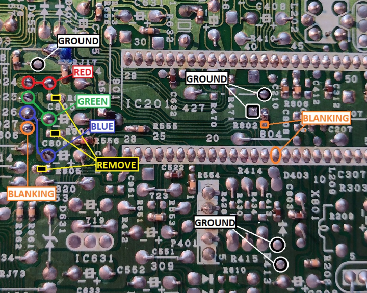
+5v points for blanking can be found near the microcontroller chip.
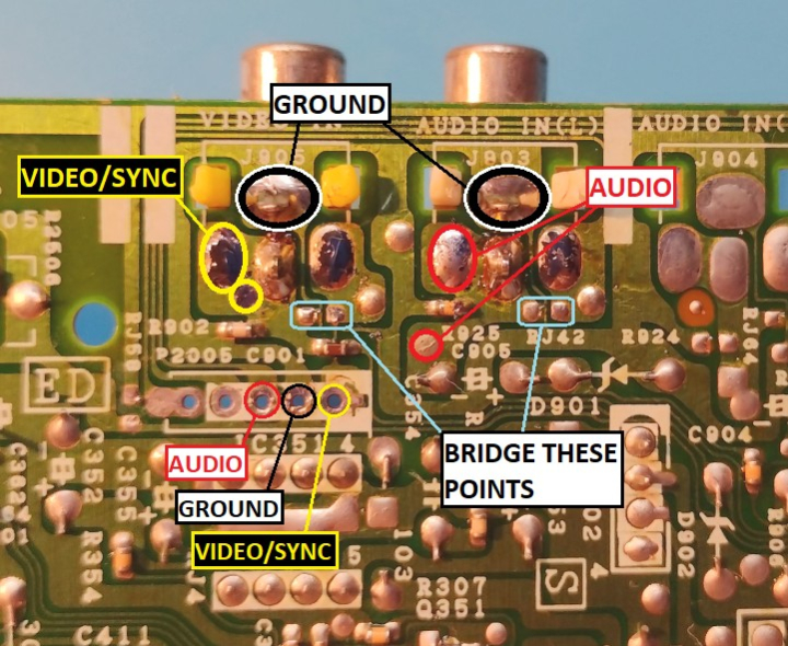
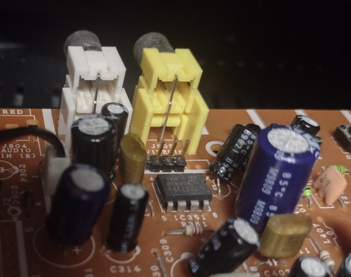
Solder points for sync, audio, and ground are on the bottom side of the front A/V jacks. This part of the PCB also has two sets of jumpers that can route the A/V inputs to an empty DIP header. If these are bridged, a 3-pin header can be installed on the top of the board, providing a convenient attachment point.
Optionally, there is an empty spot for a 9-pin DIP header at the edge of the board near the jungle chip. Seven of these pins aren't connected on the board, so this is a great place to install a pin header for the RGB and blanking connections. The following photo shows the pin layout I used (note that pin 6 is already attached to ground). Do not use pins 1 or 2.
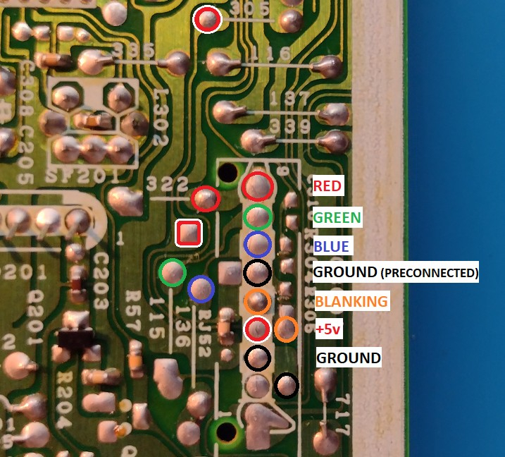
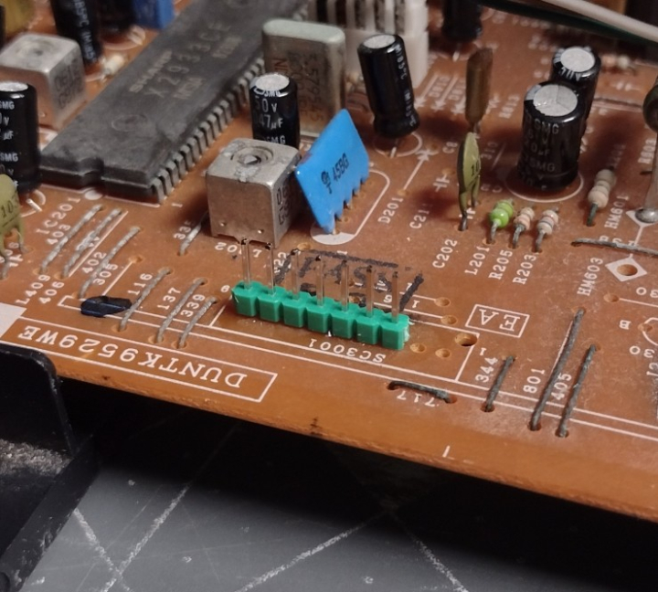
With the two headers installed, the RGB signals along with blanking, +5v, and ground are connected from the jungle chip to the 7-pin header using 26 gauge ribbon cable.
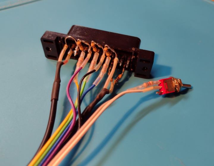
The SCART connector is wired up with all ground pins connected together, 100 ohm termination resistors installed, and 1000 ohm mux resistors inline with the RGB leads. For more information, visit the SCART installation guide.
The 1000 ohm resistor is attached to one pole of the blanking switch. I used ribbon cable for RGB and blanking, and shielded cable for sync and audio.
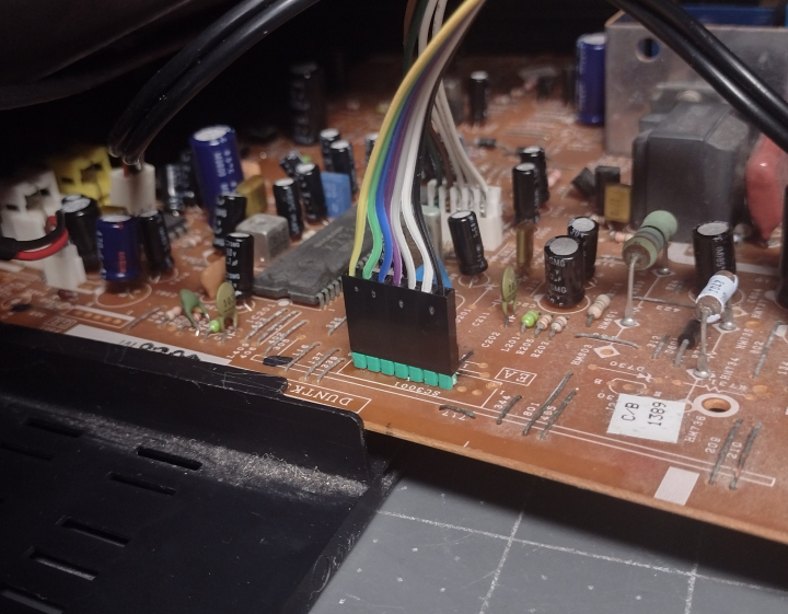
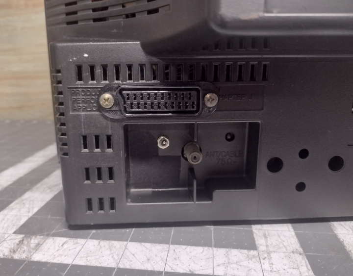
The SCART connector fits nicely above and to the left of the RF tuner. This position keeps the wiring away from the power supply and flyback transformer, which can cause interference.
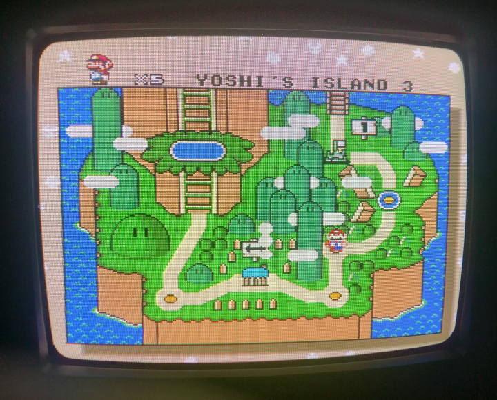
Now that the mod is done, the TV will display a clean RGB image when the blanking switch is enabled and the TV is set to A/V input. However, at this point the picture will not have proper black levels or orientation. Dark parts of the image will be crushed, and the picture will be shifted horizontally. To correct the horizontal position, refer to pages 8 and 9 of the service manual and put the TV into service mode. Adjust S07 (Horizontal Phase) until the picture is centered.
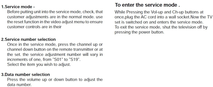
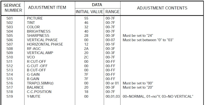
Due to the design of this TV's jungle chip, brightness and contrast levels for RGB cannot be adjusted with the user menu. Calibrating the picture requires the use of the screen pot on the flyback, and the RGB cutoff settings in the service menu.
First, the contrast level should be adjusted using the screen pot on the flyback. This is the lower of the two potentiometers on the back of the flyback. Fortunately, this TV has access holes in the back of the case, so this can still be done (using a narrow screwdriver) after the TV has been reassembled.
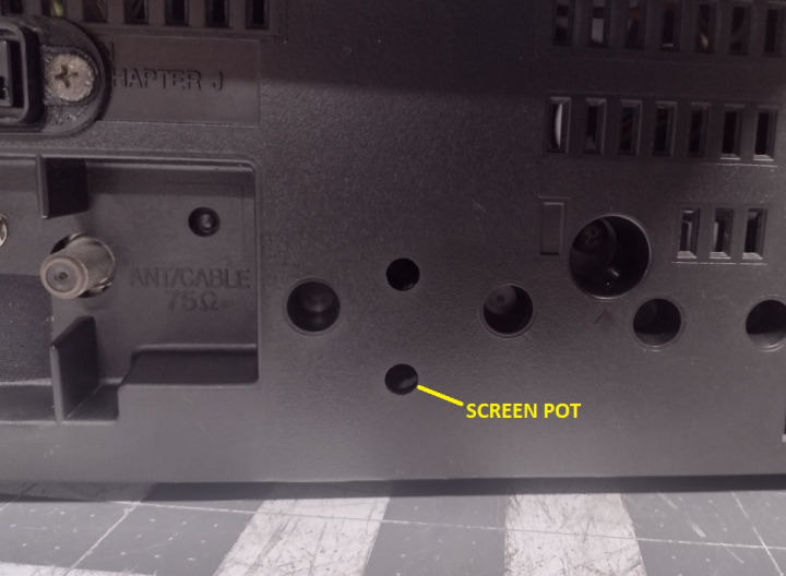
The pot should be adjusted so that the picture is nice and bright, but not bright enough to have noticeable distortion. This TV has poor voltage regulation, so excessively bright images will cause warping.
Next, the black level of the picture need to be set. To do this, it's best to use a test pattern such as the 240p test suite's "color bars" screen. Enter the service menu and adjust the red, green, and blue cutoff values (S11, S12, and S13) so that the background of the test pattern is still black, and the lowest levels of the color bars are barely visible. Raise all 3 cutoffs by the same amount (the inital values of each will be slightly different, as the TV's color balance was calibrated at the factory). On my TV, I had to raise the cutoffs to 40 (hex) over their initial values to get a good picture, but every TV will be different.
Finally, the brightness and contrast levels for composite will have to be readjusted. After calibrating the picture in RGB, switch to the composite input and reduce contrast and brightness in the user menu so that the picture is at the proper brightness. If the user menu adjustments aren't sufficient, go to the service menu and adjust sub brightness (S04) and sub picture (S01).
 This work is licensed under a