Sony BA-4D 27" Chassis RGB Mod via OSD Mux
Written by Matt Ross (6tanks)
Sony's BA-4 and BA-4D chassis designs can be modded for RGB input via the on screen display (OSD) circuit. This provides a noticeably cleaner picture than S-Video or composite, and comes close to the image quality of their larger PVM monitors.
The TV pictured in this guide is a KV-27S42. It should apply to any of the 27" BA-4D Trinitrons, including the 27S46, 27S66, 27V42, and 27V66. The 13" and 20" models use a different PCB design, so some details will be different.
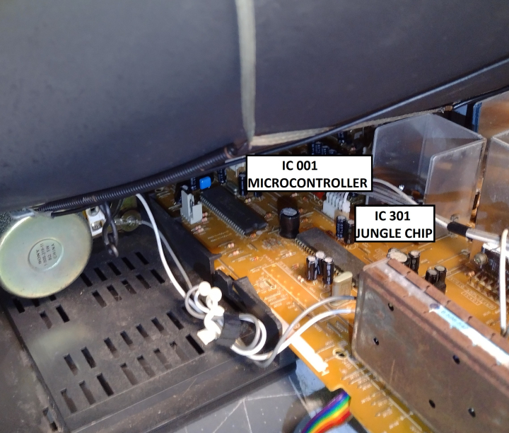
On these TVs, the microcontroller and jungle are located on the A board, near the front of the TV by the right speaker. Most of the work will be done in this section and near the A/V port.
As can be seen in the service manual, each OSD signal passes through a voltage divider and a 0.01uF coupling capacitor on its way to the jungle chip.
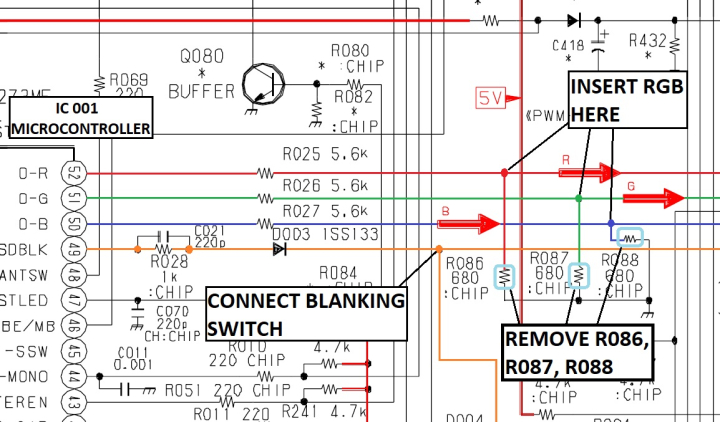
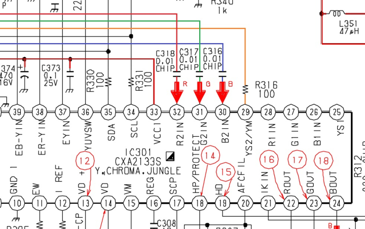
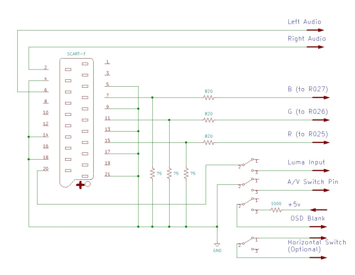
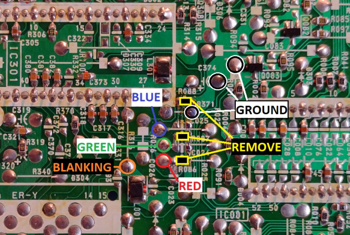
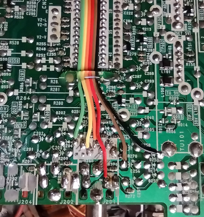
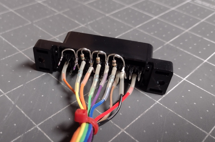
To insert our RGB signals, we need to remove the 3 resistors to ground (R086, R087, and R088), and connect the RGB signals before they pass through the 0.01uF capacitors. Each RGB line must have a 75 ohm terminating resistor to ground and, to maintain OSD function, an 820 ohm inline resistor before connecting to the chassis. Sync (ideally in the form of composite video or luma) should be connected to the Luma pin of the S-Video input, as the comb filter used by the composite inputs will cause excessive horizontal shift in the picture.
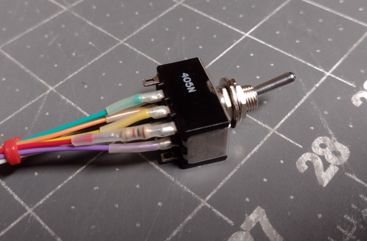
For the blanking switch, a 4PDT switch should ideally be used, although a DPDT switch can suffice. Blanking should be connected to a +5v supply via a 1000 ohm resistor. To enable the S-Video input for sync, there is a pin on the S-Video port that must be connected to ground. If needed, the sync signal can be run through one pole of the switch so that it's disconnected when RGB is not in use. And, optionally, the 4th pole of the switch can be connected to the horizontal position switch so that screen position is maintained when switching from RGB to S-Video or composite. If using a SCART connector, wire it up as follows:
The 3 resistors that need to be removed are located near one corner of the jungle chip, along with attachment points for RGB, blanking, and ground.
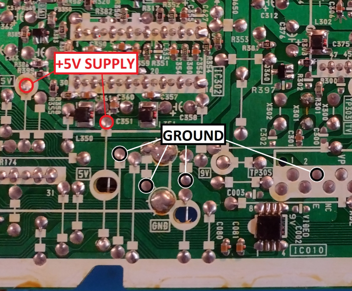
+5v points for blanking can be found near IC 302, the smaller chip just behind IC 301.
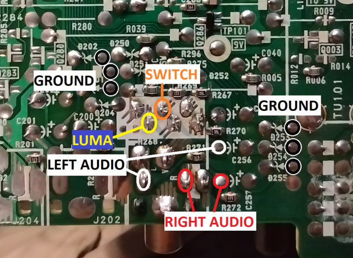
Audio signals, Sync, and the S-Video switch can be routed to the bottom of the AV input connectors.
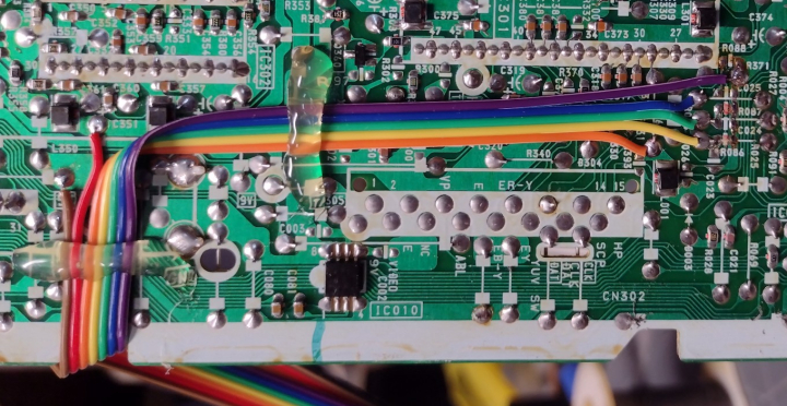
I used 26 gauge ribbon cable for wiring, secured with a bead of hot glue and routed off the left hand side of the PCB. It's a good idea to use quick connects so that the back case can be easily removed.
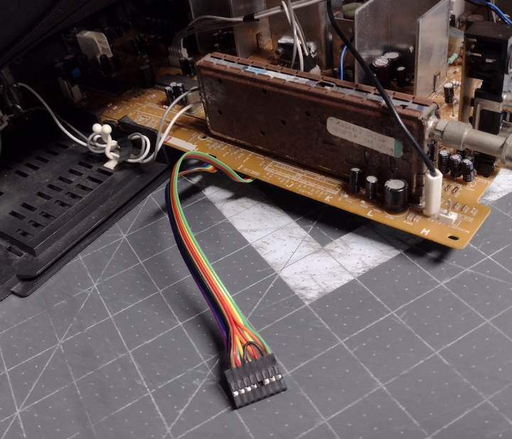
The SCART connector is wired up with all ground pins connected together, 75 ohm termination resistors installed, and 820 ohm mux resistors inline with the RGB leads. For more information, visit the SCART installation guide.
Sync, S-Video mode switch, and blanking are connected to a 4PDT toggle switch. The 1000 ohm resistor is attached to one leg of the blanking switch.
On KV-27S42, S46, and S66 models, there is a small white 3-position switch near the yoke connector that controls horizontal position. It is not present on the KV-27V42 and V66.
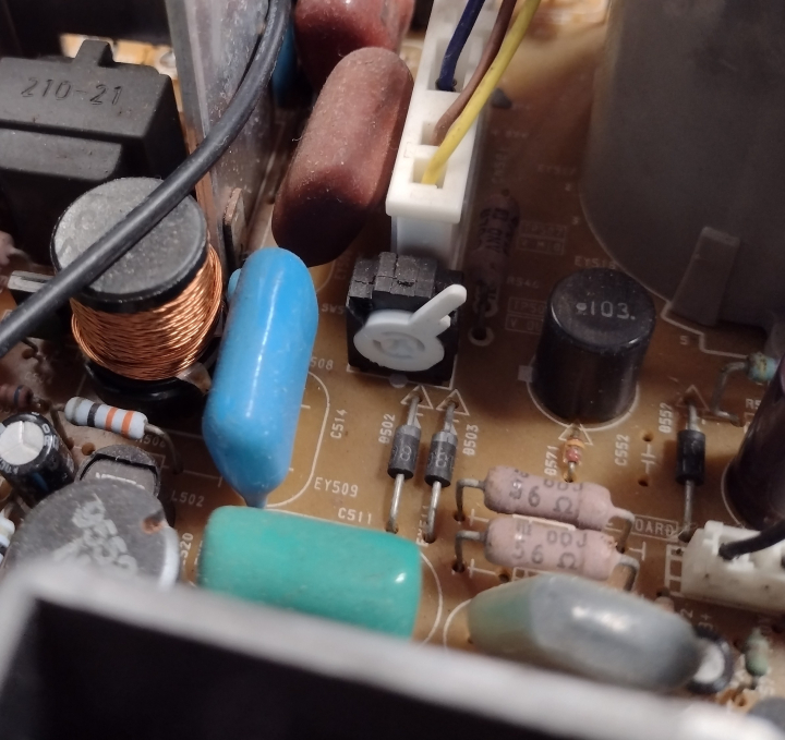
This switch can, optionally, be connected to 4th pole of the blanking switch to compensate for the horizontal shift in the picture when switching to RGB. To use it, the switch must be in the right position (as seen in the above photo). Now, connect two wires to the 2nd and 4th pins on the bottom of the PCB. These should be wired so that the switch is open when blanking is enabled and closed when it is disabled (opposite to the other 3 poles). Heavier wire such as 24 or 22 gauge should be used.
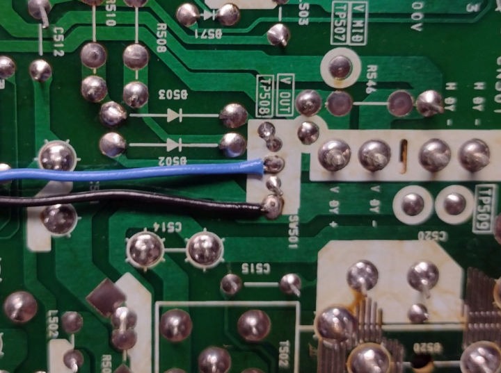
The position switch wires can be routed through a small hole to the top of the board and connected to the blanking switch with a quick connect.
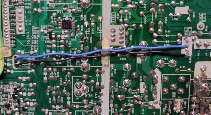
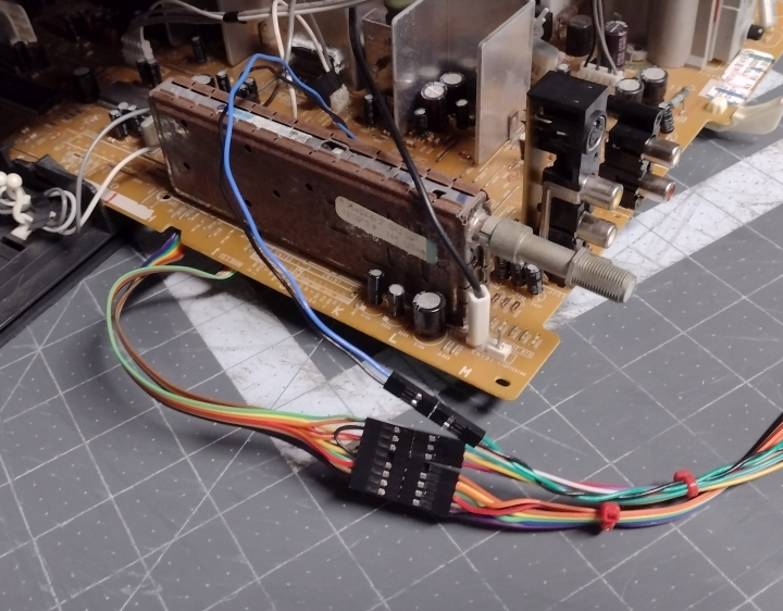
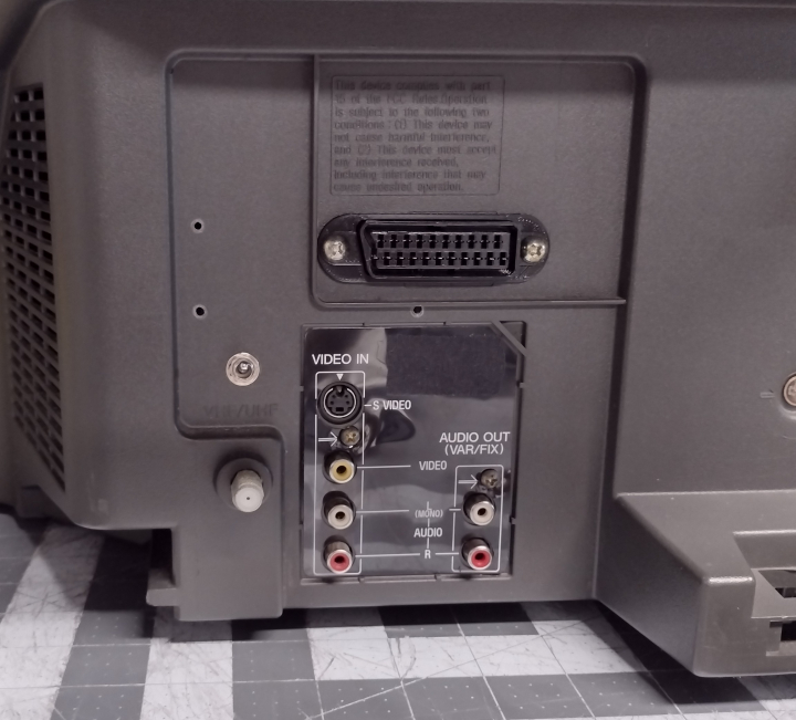
The SCART connector can be neatly mounted above the A/V inputs, or vertically in the space above the tuner.
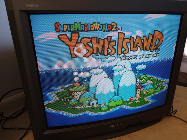
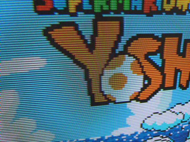
Now that the mod is done, the TV will display a clean RGB image when the blanking switch is enabled and the TV is set to the correct A/V input. The picture may be shifted horizontally somewhat. To compensate for this, refer to the service manual and adjust HPOS so that the image is centered. If the horizontal position switch has been connected properly, the picture should remain centered in both RGB and A/V modes, otherwise it will have to be manually adjusted when changing input types.
NOTE: The V42 chassis has an issue with RGB "streaking" where you will see ghosting/streaks/tails coming off the right side of bright white things like text. To fix this, go into the setup menu and change the PICTURE mode to "VIVID". Then turn the PICTURE slider down to about 65-75%, whatever looks best to you. The streaking should be completely gone.
 This work is licensed under a