Sony KV-13M20
March 8, 2024, 11:13 am
July 29, 2025, 12:07 pm
Summary
Despite the name being so close to the KV-13M10, this is a newer chassis revision (BA3) which is not RGB moddable. The OSD is digital RGB and the chroma chip cannot be swapped with any other known model number to get analog RGB capabilities back. Despite this, the chassis can still be S-Video modded fairly easily, which still allows for very good picture quality on a 13" tube.
Manuals
Notes
The inside sticker mentions that this chassis is compatible with both the A34JBU70X and A34JBU10X tubes - which suggests these tubes are swappable. You may be able to use this 70X tube as a salvage for a PVM that takes the A34JBU10X tube.
Sony BA-3 Chassis S-Video Mod
Updated August 14th 2025.
You will need:
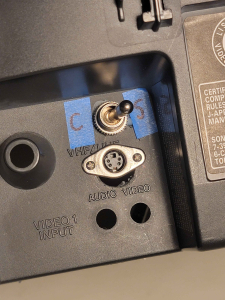
- SPDT toggle switch (or a DPDT with one side bridged together to make it SPDT)
- S-Video panel-mount socket. I suggest buying from Digi-Key or Mouser, the Amazon ones don't last very long.
Steps for mod:
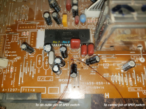
- Desolder and completely remove the jumper which is in the position labeled R308.
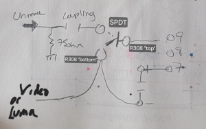
- The "top" pad of R308 (nearest to the "R" of "R308") must be wired to the single pole (SP) side of your switch.
- Your chroma input signal MUST be terminated and coupled. This means you need to wire in a 75ohm resistor from the input to ground, and then place a 0.1uF capacitor after in series. Finally connect a wire between your coupling capacitor to one of the two remaining pins on the DT side of your SPDT switch.
- Connect a wire from the other pad of R308 to the last remaining DT pin of your SPDT switch.
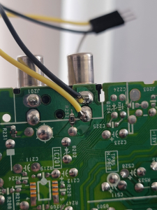
- Connect your Luma input signal wire to the input pad for Composite Video (see image).
- Connect your Ground wire to the ground pad for Composite Video (see image).
- Enter the service menu by (while TV is off) pressing the following sequence on the remote, one at a time: Display + 5 + VOL-UP + Power. Scroll the settings with 1 and 4 on the remote until you find "CROM" or "CTRP". These should be set to 0, if your service menu has them.
If wired correctly, your SPDT switch should now be switching between "stock" configuration of the circuit, and terminated coupled s-video chroma injection. The reason this switch is necessary is because the termination resistor would break normal composite video processing, because it shared the Y input of the jungle. So our switch changes input to the Y pin between the stock composite circuit and our injection signal. Note that "CROM" or "CTRP" should be turned back on (1 instead of 0) when using composite. The silkscreened numbers for the pins of the jungle chip on the PCB are not correct as the chip is offset by 3. For example, the pin labelled 10 is actually 7.
Don't have consoles connected to both input sources at the same time, otherwise your signal brightness may be raised/lowered dramatically due to termination problems.
Gallery
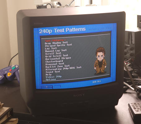

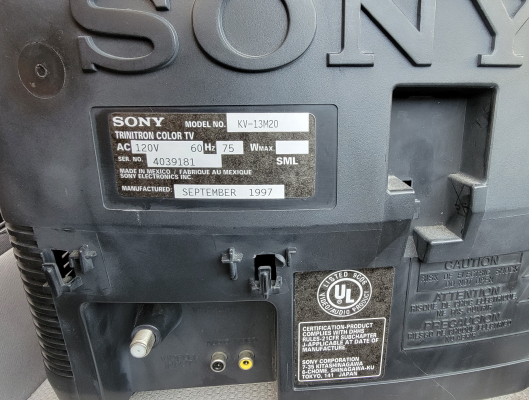
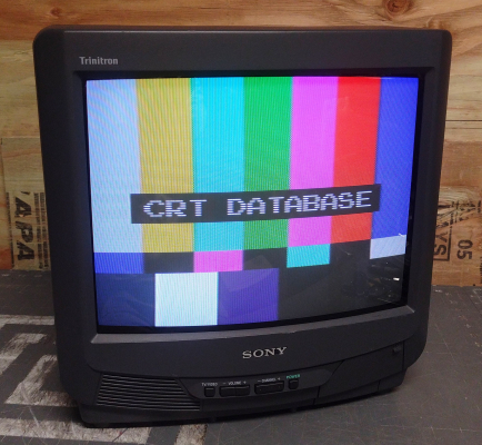
| Specifications | |
|---|---|
| Brand: | Sony |
| Manufacturer: | Sony |
| Model: | 13M20 |
| Series: | KV |
| Viewable Size: | 13" |
| Input Signals: | Composite, RF |
| Native Resolutions: | 240p, 480i |
| Formats: | NTSC |
| Aspect: | 4:3 |
| Adjustments: | OSD Customer Controls, OSD Service Menu |
| Jungle IC: | CXA1870S |
| Flyback: | NX-1731, 8-598-962-00 |
| Tube: | Sony Trinitron , A34JBU10X , A34JBU70X |
| Mask: |
Aperture Grille

|
| Tint: | Dark |
| Speakers: | Mono |
| Remote: | RM-Y146 |
| Chassis: | BA-3 |
| Weight: | 22 lbs (10 kg) |
| Application: | Consumer |
| Launched: | 1996 |
| Country of Manufacture: | Mexico |
| Mods: | S-Video |
| Degaussing: | Automatic on Power-on |
 This work is licensed under a