Sony KV-13TR24
August 25, 2024, 6:00 am
October 18, 2025, 7:58 pm
Summary
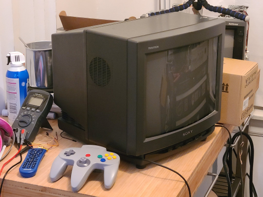
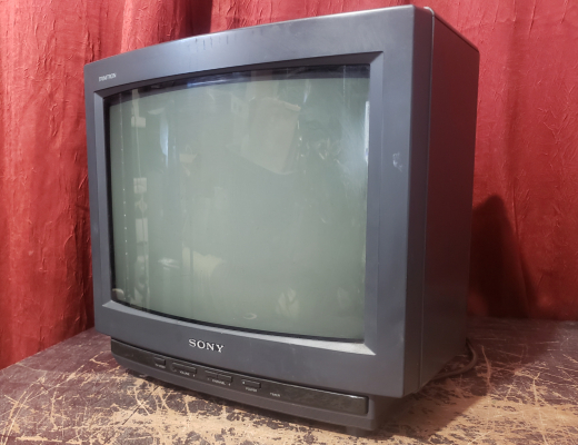
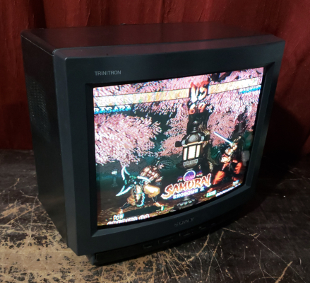
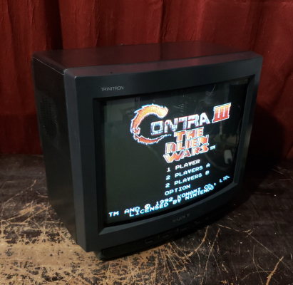
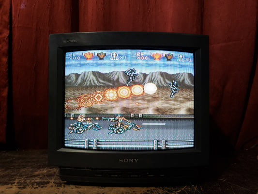
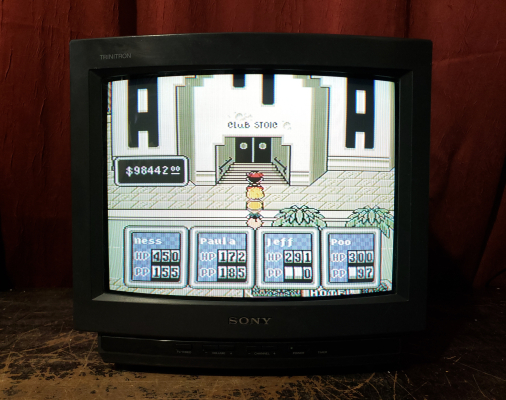
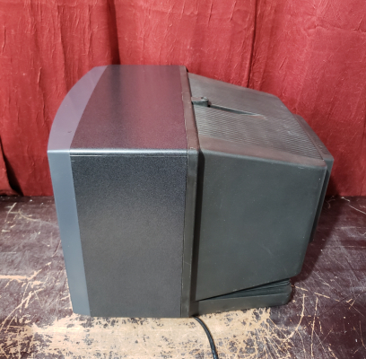
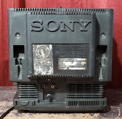
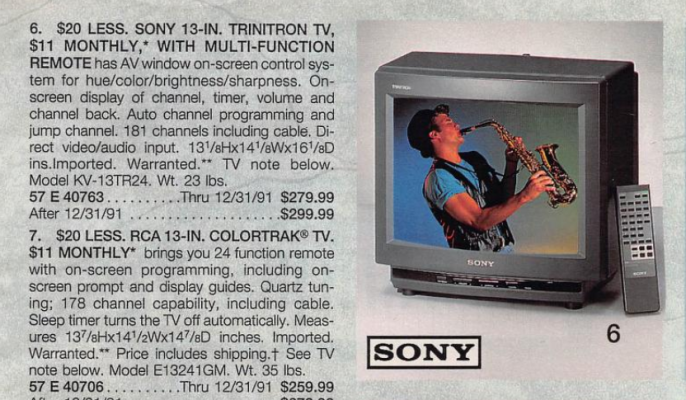
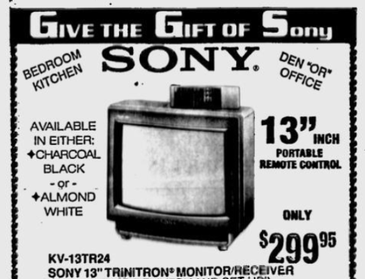
Standard consumer-level trinitron from the early 90s. OSD runs separate from jungle, jungle has no analog RGB inputs. Unamplified RGB injection is not possible. S-Video mod is possible (see below). Came in two colors, charcoal black and almond white.
Manuals
Media & Promo Materials
Mods & Repair Guides
Notes
The following models all share the same service/user manuals: 13TR14, 13TR24, 13TR27, 1427R, 13EXR90, 13EXR91
Repair Notes
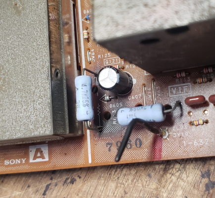
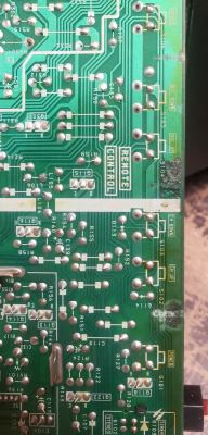
Even when the set is in standby there are two resistors that get quite hot to the touch (R613), and there is an electrolytic capacitor that is prone to failure due to being next to them, C607. When replacing C607, recommend leaving the capacitor with long legs extending it away from the board and leaning away from the heat of the adjacent resistors. Two different units of this model were found to have distorted low end sound, and one had a blown speaker. In the audio circuit, distortion first becomes evident between R424 and IF201. I did not determine which component was faulty, possibly the VIF IC, a Sony CXA1100BS. One unit also had corrosion on the bottom of the main board that was eating through traces by the front microswitches. (-E.K.)
Gallery

| Specifications | |
|---|---|
| Brand: | Sony |
| Manufacturer: | Sony |
| Model: | KV-13TR24 |
| Series: | KV |
| Viewable Size: | 13" |
| Inputs: | Composite, RF |
| Native Resolutions: | 240p, 480i |
| Horizontal Scan Range: | 15 kHz |
| Vertical Scan Range: | 60 Hz |
| Formats: | NTSC |
| Aspect: | 4:3 |
| Adjustments: | Internal Potentiometers, OSD Customer Controls |
| Horz. Output Transistor: | D2089 |
| Vertical Output IC: | KA2131 |
| Jungle IC: | CXA1013AS |
| Comb Filtering: | None |
| Flyback: | 1-439-483-11, NX-1710 |
| Focus Type: | Single |
| Tube: | Sony Trinitron , A34JBU10X , Mirrorblack |
| Heater Voltage: | 6.3v |
| Deflection: | 90° |
| Mask: |
Aperture Grille

|
| Tint: | Dark |
| Removable Glare Film: | No |
| Yoke: | 1-451-234-12 |
| Yoke Horz. Inductance: | 3.931 mH (@ 10 kHz) |
| Yoke Vert. Inductance: | 20.75 mH (@ 100 Hz) |
| Yoke Horz. Resistance: | 5.96 ohm |
| Yoke Vert. Resistance: | 11.78 ohm |
| Speakers: | Mono |
| Remote: | RM-781 |
| Chassis: | P-3B |
| Weight: | 23.4 lbs (10.6 kg) |
| Application: | Consumer |
| Cabinet Material: | Plastic |
| Launched: | 1990 |
| MSRP: | 349 USD |
| Country of Manufacture: | Mexico |
| Market: | North America |
| Power Standard: | 120v |
| Mods: | S-Video |
| Degaussing: | Automatic on Power-on |
| Tag: | Needs Measurements, Repair Log |
 This work is licensed under a