Summary
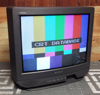
Basic 20" Trinitron, with mono audio and two A/V inputs.
Manuals
Notes
This TV was also sold in a stereo version, KV-20S40 (Black) and KV-20S41 (White). A higher end model with the same chassis, the KV-20V80, had side mounted speakers and S-Video input.
The jungle chips used in BA-4 and BA-4D chassis Trinitrons are very versatile. As such, these TVs can be modified for RGB, Component video, and S-Video inputs. When modified, picture quality on these TVs is exceptionally sharp.
Component Video Mod
Written by Matt Ross (6tanks)
Sony's BA-4, BA-4C, BA-4D, and BA-5 chassis TVs all use jungle chips that have component video (YPbPr) input capability. In some cases, these are used for the picture-in-picture (PIP) feature, but in most models they're not active. In all of these TVs, however, they can be used to introduce an external component video signal. The mod is simple and provides very clean video quality.
The TV pictured in this guide is a KV-20M40. With minor differences, it should apply to other 13" and 20" TVs with this chassis design (KV-20S40, KV-13M40).
On these TVs, the microcontroller and jungle chips are located on the A board, near the front of the TV by the right speaker. Most of the work will be done in this section and near the rear A/V port.
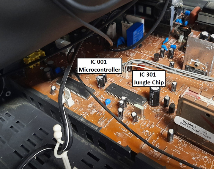
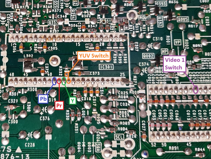
IC 301 is a Sony CXA2061S jungle chip, and the area we're interested in is pins 36 to 39. On this model of TV, they aren't connected to anything.
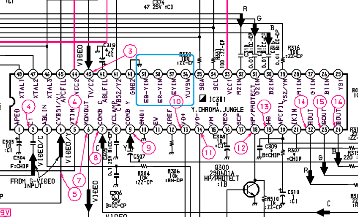
Information on their function can be found in the CXA2061 datasheet. Pin 36, YUVSW, functions as a blanking input and will switch the chip to YPbPr when a voltage greater than 0.7V is applied. Pins 37, 38, and 39 are for Y, Pr, and Pb inputs respectively. It's important to note that the jungle chip doesn't take sync through the E-Y input pin.
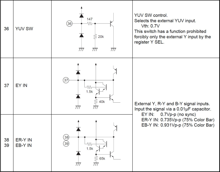
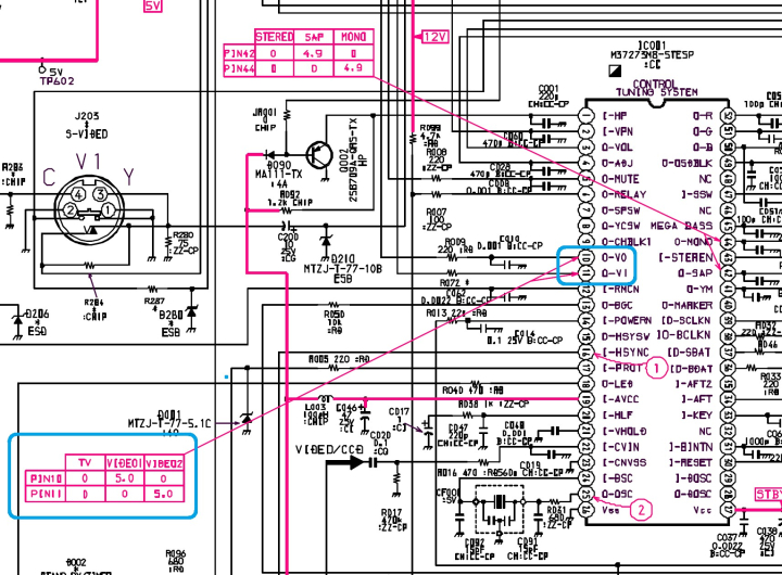
One other useful feature of this chassis design is that it uses a 5V switching voltage for the audio input chips. This can be used to switch the TV between composite and component inputs without requiring an external switch. When 5V is applied to pin 10 of the micon chip (IC 001) when Video 1 is selected, and pin 11 for Video 2. By connecting pin 10 to the YUVSW input pin on IC 301, it effectively converts the rear AV input to component, while still allowing composite on the front of the TV.
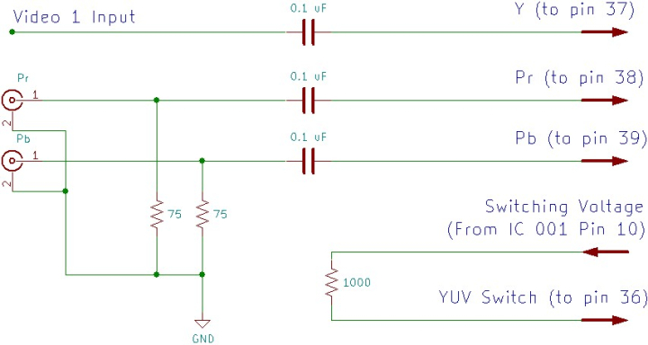
For this mod, only two additional RCA jacks need to be installed, for the Pr and Pb signals. Each of these inputs requires a 75 ohm terminating resistor to ground, and an inline coupling capacitor (0.1 uF works well). These can then be connected to pins 38 and 39 of the jungle chip.
Because the E-Y input pin does not process sync, the Y signal must be split between pin 37 of the jungle chip and the TV's composite input. This will allow it to sync properly, while also routing the luma signal to the right place for component video. The easiest way to do this is to connect pin 37 to the rear A/V input on the bottom of the PCB (also using a 0.1 uF coupling capacitor), and use the original composite jack for the component Y input. Because the A/V jack is already properly terminated, it does not require an additional 75 ohm resistor.
To allow the TV to switch between composite and YPbPr automatically, connect pin 10 of the micon chip (IC 001) to pin 36 of the jungle chip. A 1k ohm inline resistor can be added for safety. It's also possible to use a manual switch instead, which may be preferable if you'd like to keep the option of using the rear A/V input for composite. Also, the 13" models don't have a front AV input and will require a manual switch unless composite is no longer needed. Pin 36 can be connected to a +5V point on the board through a SPDT switch.
The mod is represented in the following schematic:
Attachment points for the video signals & blanking are directly on the jungle chip & microcontroller:
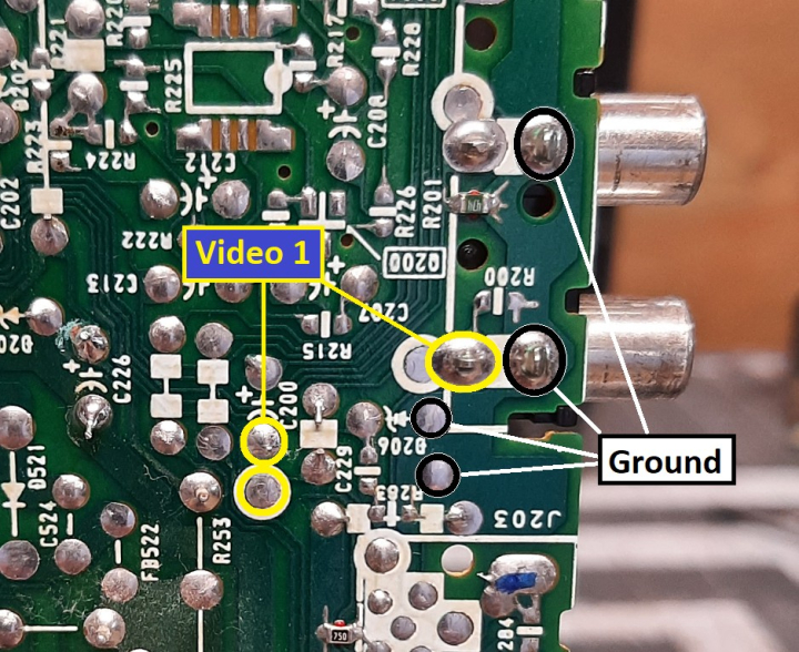
The rear AV input section has solder points for the Video 1 composite input and ground:
I used 26 gauge ribbon cable for wiring, which is a good size for soldering to the jungle chip pins:
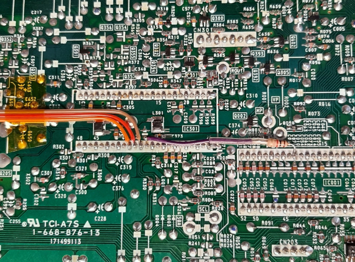
This can be routed to the back of the chassis PCB, secured with Kapton tape, and attached to the Video 1 composite input through a coupling capacitor. The Pr and PB lines can be passed through one of the small holes in the board, or over the left hand edge by the tuner.
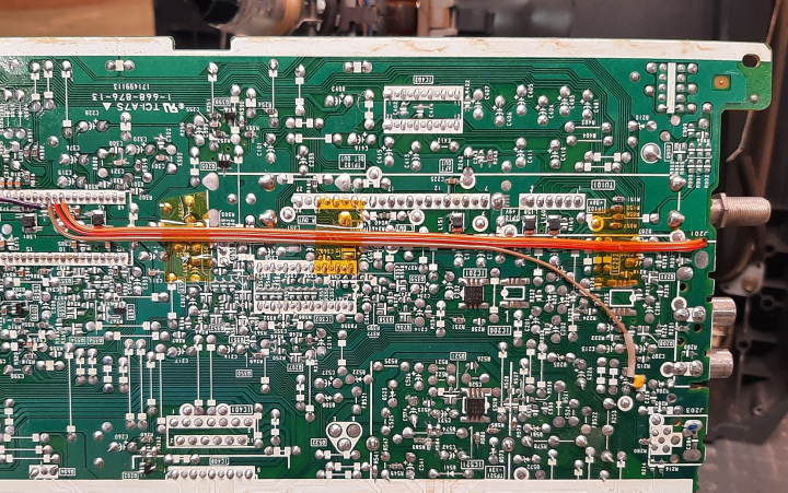
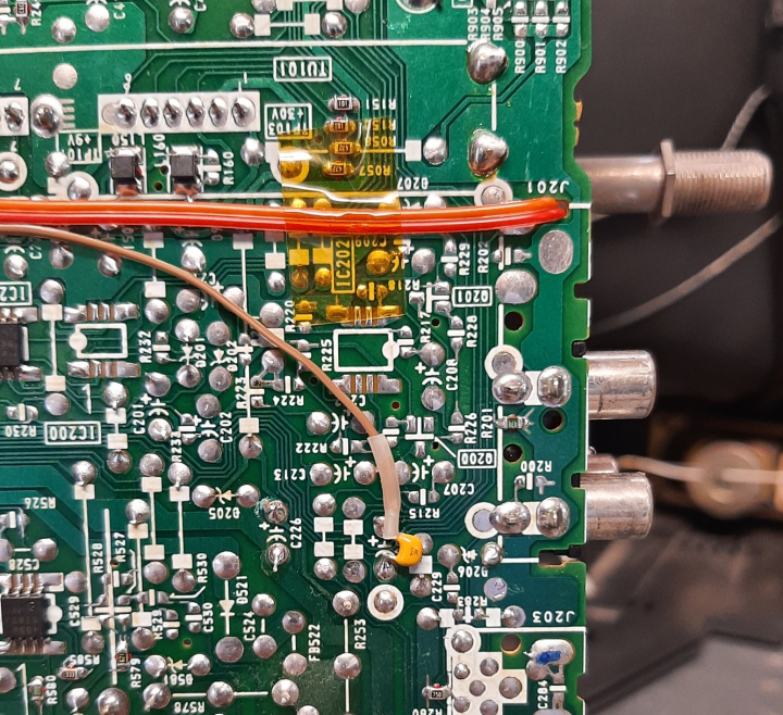
The terminating resistors, coupling capacitors, and ground lines for the Pr and Pb signals can be attached to the input RCA jacks. For this mod, I used a pair of RCA jacks salvaged from another TV and glued to the top of the composite input. However, it would have been simpler to just use panel mount RCA connectors. With that method, quick connects would be necessary to allow removal of the back case.
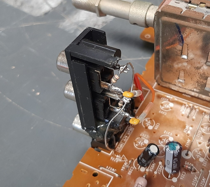
If desired, the rear composite input can be colored green with a permanent marker to match the rest of the connectors.
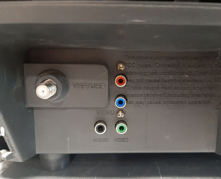
Now that the mod is done, the TV will display a very clean image through component video cables when the input is set to Video 1. The picture may be shifted horizontally somewhat. To compensate for this, refer to the service manual and adjust HPOS so that the image is centered.
NOTE: With this mod, chroma and black levels will not match the original composite video input. This is due to the sync pulses on the luma signal, which cause it to be clamped at the wrong level by the jungle chip. This can easily be corrected in the user menu by reducing brightness and increasing color saturation. This will have to be readjusted when switching back and forth from composite.
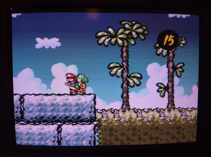
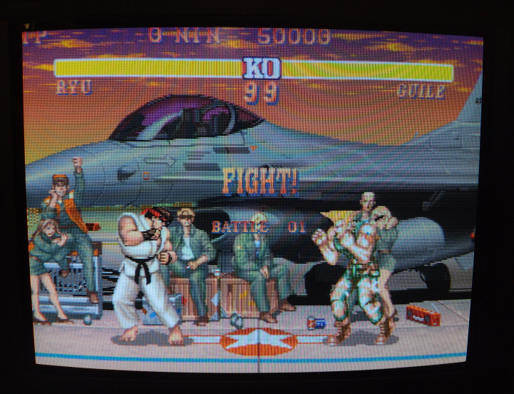
Gallery



 This work is licensed under a