P3 Chassis S-Video Mod
This chassis, like many other TVs of the same generation, does not have an isolated power supply design - which makes traditional mod methods unsafe due to floating ground potentials. The way composite video is safely fed into this chassis is via opto-isolation, which uses a floating connection to transmit the video info without sharing a common ground point. This method is the safe way to add additional inputs to these types of TVs, and finally Kaz Packman aka KPackratt2k has designed a PCB to facilitate this for S-Video modding. Below are his instructions for the mod.
PCB Purchase
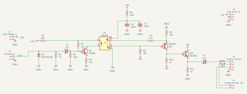
Schematic
Notes
You can solder the wires for power and ground on the AV input board (or the U board) and run them to the Chroma isolation board via JST connectors. I forgot to take photos of the tap points, but the cold side shares the ground with the AV inputs whereas the hot side does not. The wires for Chroma go to the chassis (or the A board), you'll have to lift the Chroma coupling capacitor (C357) from the side that connects to pin 39 of the jungle chip (IC301).
To reduce the risk of interference, I strongly recommend using shielded wire for the ends of the Chroma connections that send it to the jungle chip. When I prototyped this mod, I was getting noise that sometimes affected color intensity on the S-Video input when I used unshielded wire. Using shielded wire instead eliminated the noise and kept the color intensity consistent with the stock Composite video input.
As for a place to mount the Chroma isolator board, there's an empty space in the cabinet where the chassis boards are mounted, the empty space is located near the input board (the U board), providing a convenient spot to mount the isolator board using 3M VHB double sided tape to hold it in place. It is recommended to place two layers of kapton tape on the board before putting the double sided tape on it.
Connector labels on the Chroma isolator board and their tapping points on the TV:
- Cold power and ground (the 2-pin JST on the top-left of the isolator board):
- VCC (Cold Side) <- Cold 9.2V (The positive leg of C1405 connected to R1428 on the U board.)
- GND (Cold Side) <- AV input ground or IC1401 pin 10
S-Video Chroma input (the 2-pin JST on the bottom-left of the isolator board):
- C_IN <- S-Video Chroma (Pin 4)
- GND -> Ground point for shielded wire, can also go to the ground pins of the S-Video jack (the shield and pins 1-2.)
Hot power and ground (the 3-pin JST on the top-right of the isolator board):
- VCC (Hot side) <- Hot 9.3V (connected to pin 1 of IC1401 via R1403 or U-2 pin 5, should be labeled accordingly on the U board.)
- Middle pin is not connected to anything.
- GND (Hot side) <- IC1401 pin 5 or any ground outside of the cold area of the U board on the TV.
Chroma I/O from the TV chassis (the 2-pin JST near the 4-pin JST on the bottom-right of the isolator board):
- YCJ_IN <- IC301 pin 39, can inject to the pad where C357 was lifted, connecting to this pin on the chip.
- TV_C <- C357 coming from the emitter of the TV Chroma buffer (Q357).
Chroma I/O to an SPDT switch (the 4-pin JST on the bottom-right of the isolator board):
- C_OUT -> Pin 1 of the switch
- YCJ_IN -> Pin 2 of the switch
- TV_C -> Pin 3 of the switch
- GND -> A grounding point for shielded wire, provided for convenience.
Luma (S-Video pin 3) simply goes to the Composite video input.
You'll have to be strategic for finding a place to mount the S-Video jack and the Chroma switch. I've decided to relocate the RF tuner I/O panel somewhere else and run a short Coax cable from the VHF/UHF input to a coupler mounted in the VHF/UHF input's original hole. The S-Video jack is mounted on the "Aux" input on the left, though the plastic on the back side of the jack panel plate had to be shaved to allow for the panel mount jack to fit without the nut coming off. I mounted a spare panel mount SPDT slide switch in the "To Converter" hole in the middle of the jack panel to serve as the switch to toggle between S-Video and Composite video/RF.
When/if I get ahold of more Sony TVs from the same era, I'll be sure to test the mod board on those models and document any specific instructions that apply to them. I've also been working on replicating the S-Video switching circuitry from the KV-27TS30 to implement on other models with the same chassis for either using a SPST switch or a completely switchless mod using an S-Video jack with its shield cut in half to connect one side to ground and the other side to a high/low logic signal.
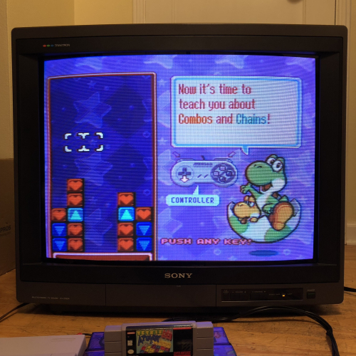
Result
 This work is licensed under a