Summary
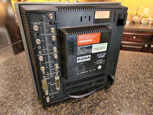
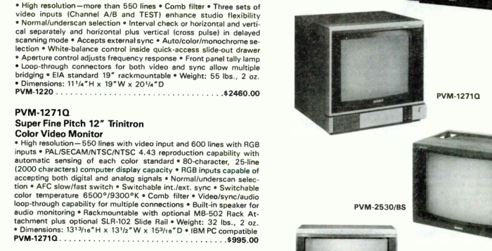
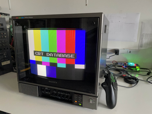
Small, high resolution 15Khz PVM from the early 80s. Surprisingly high TVL and has analog RGB inputs + supports all video signal formats including SECAM.
Manuals
- Owner's Manual
- Service Manual
- Better Service Manual - this is the 1371QM but the circuits are essentially identical. This PDF also has the missing waveform pages and other supplemental materials missing from the US scan.
Repair Notes
N and U labeled adjustments on D board
Most deflection board adjustments have a pair of potentiometers assigned to them - one with an N prefix and one with a U prefix. For example, N H WIDTH and U H WIDTH.
- The N stands for "Normal" and only applies when the underscan switch is set to "Normal" on the front of the PVM.
- U stands for "Underscan" and only applies when the underscan width is set to "Underscan" on the front of the PVM.
Refer to the service manual for specific directions on adjusting these.
Pincushion / H-Width failure
There is a very common failure on this model related to pincushion / h-width. Symptoms can range anywhere from slightly reduced max horizontal width (can't fill the gaps on the sides of the screen) to severe pincushion collapse where the picture looks similar to the shape of a squished pillow.
Check the following, in order. Keep working down the list until your issue is solved:
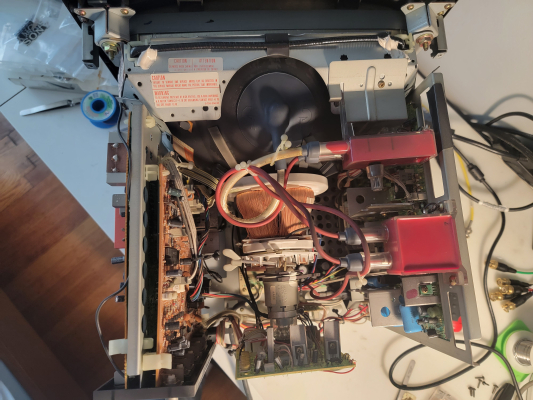
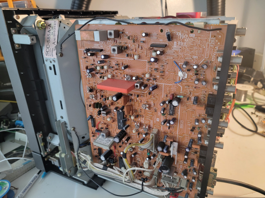
- Clean all potentiometers on the D board (right side of chasses when looking from the rear) using Deoxit F5 or similar deoxidizing spray cleaner. Try adjusting the N PIN AMP and N H-WIDTH again and observe if the picture is behaving normally now.
- As a test, desolder pin 10 of IC804 and then power on the PVM. If the raster width increases, then you have a bad component in the Pinamp circuit. To desolder the pin, simply use some solder wick and absorb all of the solder off the pad until the IC leg can be poked around freely with tweezers, etc . This will ensure there is no continuity between the IC and the circuit, allowing tests to be done earlier in the circuit. Most likely the failure component is one of the potentiometers in the pinamp adjustment circuit. Pull them out one at a time (keep track of which one is which!) and measure them out of circuit with a multimeter to ensure they still work and are within the range shown in the service manual. For example a 330ohm pot should be able to measure from 0 to 330 when turned slowly and watching on a multimeter. If you need a replacement pot, its fine to go over the original range by about 30-40% but do not ever go under the original range. The more you go over the original range the more touchy and imprecise the adjustment process will be later when you are fixing the pinamp alignment. Remember to resolder the pin for further testing later.
- As a test, desolder pin 11 of IC804 (resolder pin 10 back in from the last step) and then power on the PVM. If the raster width increases, then you have a bad component in the Pin Phase circuit. Check the potentiometers first, similarly to what is described for Pin 10 diagnostics above. Remember to resolder the pin for further testing later.
- If desoldering those pins did not increase H width then you may have a problem with Q806, the pinamp output amplifier. The collector should have at least 30v measured on it with a multimeter. Pull the transistor and test it with your multimeter or a transistor tester to make sure its good (or just replace it). If 30v supply is missing then start inspecting nearby components for failure.
- If Q806 is working fine then you may have a dead IC804. Replace it and try again.
- The capacitors spec in this circuit are not really critical (I have seen 1271Qs working fine where the pinamp waveforms were severely rounded off and noisy from bad caps) but they do need to actually still be functional capacitors - meaning none of them can be shorted or open. You may want to spend some time checking all of these caps one by one (or just replacing them) if nothing else has worked so far.
Gallery





 This work is licensed under a