Table of Contents
Overview
The BK 490 (1989) and 467 (1973) are internally identical. The 490 is simply an '89 re-release of the tester with a more modern case appearance and updated set of socket adapters. Believe it or not the original 467 design includes one 12BH7A vacuum tube inside, which they kept for the 490 re-release! This tube is used as a shunt regulator for the 530v DC voltage for G2 testing. BK's product guide states that the 467/490 is unique because it "measures only beam current that actually passes through the G1 aperture to the screen. All three guns of a color picture tube are tested in sequence 20 times per second. Because all three guns are tested simultaneously, leakage between the elements of different guns is pinpointed immediately. Cathode-to-cathode leakage, once virtually impossible to diagnose, is displayed as positively as common G1-to-cathode and cathode-to-heater leakage."
Key Features
In addition to the standard/expected features of a CRT Tester, the 490 and 467 have these additional key features:
- Higher than average G1 bias (-30 to -100v) for highly accurate emissions readings on a wide range of tubes
- Higher than average G2 supply (0 to 350v in NORMAL setting, 180 to 530v in HIGH setting) for compatibility with a wide date range of tubes
- Cathode Leakage Detection
- Self-limiting G1 Shorts Clearing (current only flows if there is actually a short, no damage can occur to a tube without shorts)
- Low-current rejuvenation mode (called Clean & Balance)
- Full range of filament voltage choices from 0 to 15v
- Focus (G3) continuity test
- 3-gun simultaneous emissions display for color tracking
Buyer's Guide
Read the OEM-Adapters section below to learn about what adapters should come with your tester and which ones are the most commonly needed.
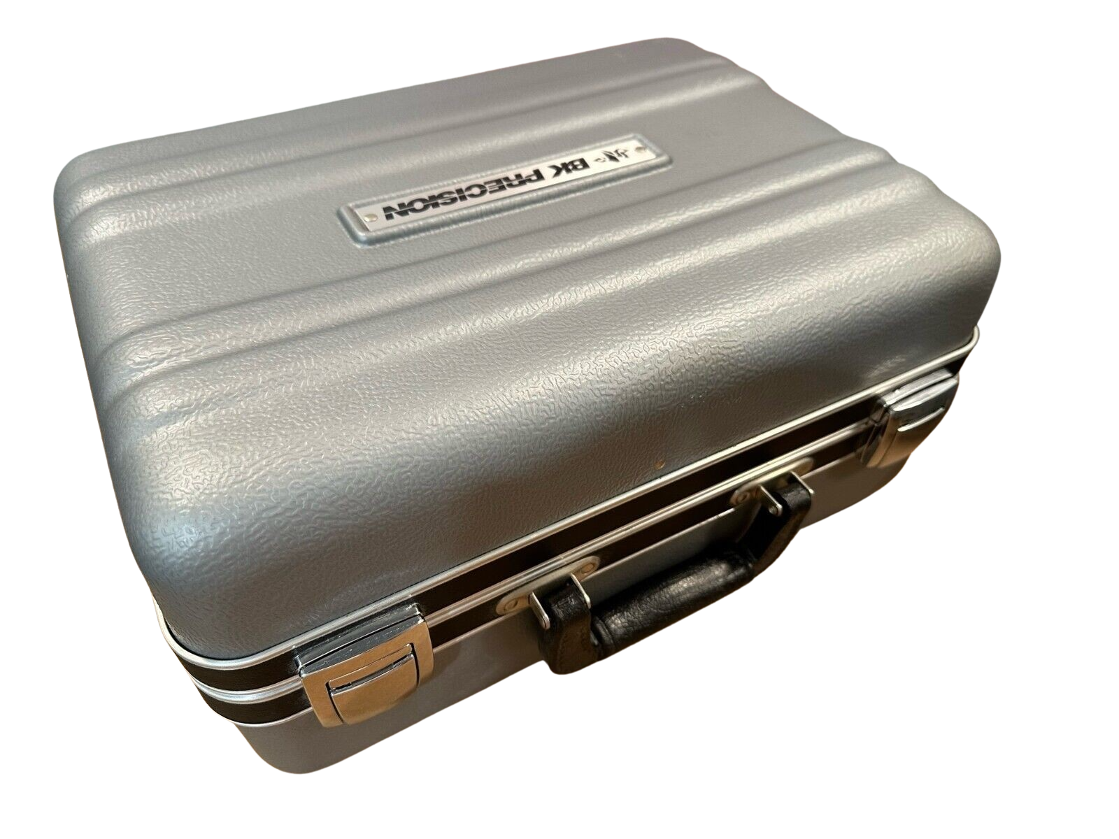
The top half of the briefcase is a storage pouch for socket adapters and if you are considering buying one, you should check to see if any adapters are included within the pouch.
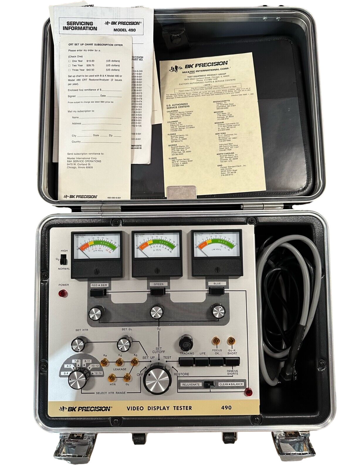
BK CRT Testers are pretty rock-solid so there's not much to worry about with their operation condition, as long as they don't look visually abused and have all of their knobs in-tact. The tester should have two wires coming out of it - one grey wire for tube connections and one black AC plug for power. The red POWER light should glow if the tester is plugged into the wall and has the center dial turned to SET-UP, and the right-hand meter should move to display the current AC voltage from the wall (~125v).
Current value for the 490/467 (as of May 2023) should be around $300-350+ if some adapters are included, or around $200-250 with no adapters included.
Tips & Tricks
The BK manuals for testing tubes over-simplify the meaning of the "Normal" and "High" setting for the G2 supply during the Cutoff step of testing. While in many cases this is true for modern tubes in solid-state chassis, it is not at all true for vintage tubes. Some older delta-gun style tubes operate at as high as 700v G2, and you won't even be able to get a cutoff reading on a new-old-stock delta gun tube unless you crank G2 into the High setting. So keep in mind what you are testing before you interpret the results you see on the tester :) Same applies for G1, sometimes you will need to do some research to know the proper voltage to set this to, BK often didn't have data from the manufacturer on specific tubes and just listed a default setting of 50v, while in reality that tube might have been using a -100v or greater G1 voltage in chassis application.
Manuals & Set-up Charts
- 467 Owner's Manual & Schematic
- 467 Service Manual
- 490 Owner's Manual (schematic is same as 467)
- Collection of all OEM Socket Adapter Pinouts
- List of OEM Socket Adapters with their common brand associations or tubes
- "Condensed Instructions" 2-page manual from BK
- CRT Set-up Chart (1989 publication date)
- CRT Set-up Chart (1999 publication date, latest one issued by BK Precision)
Maintenance Checks
Line Voltage
With the tester in SET-UP mode, verify the far-right meter reads the correct AC voltage from your wall. Compare using a reading on a multimeter. If you need to adjust this value, adjust the unmarked potentiometer right next to R20 inside the case until the reading is accurate. This reading is important because the rest of the tester calibrates itself to the line voltage.
Heater Voltage
Before using the 490 or 467 on a tube, you must verify that the heater voltage readings are correct. In order to connect a digital multimeter for measuring the voltage you have 3 options:
- Make your own CR-XA adapter and attach your multimeter probes to the clip leads for H1 and H2
- If your tester came with any socket adapters, you can connect those and then insert your probes to the heater pins of the socket. For Adapter CR-3, this would be pin 1 and 14. Each adapter has a different pinout so you will need to look up the info (see OEM-Adapters) and figure this out.
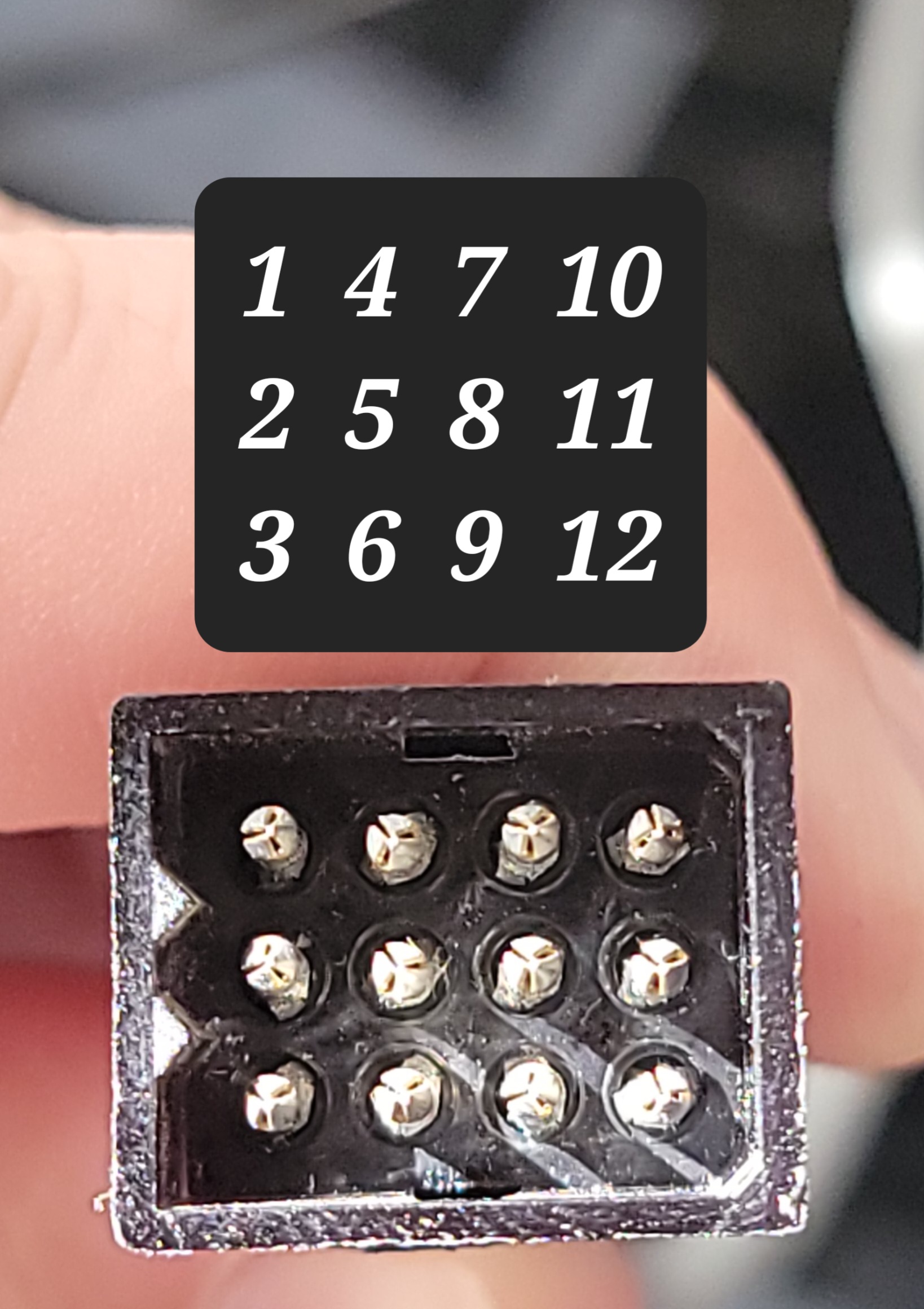
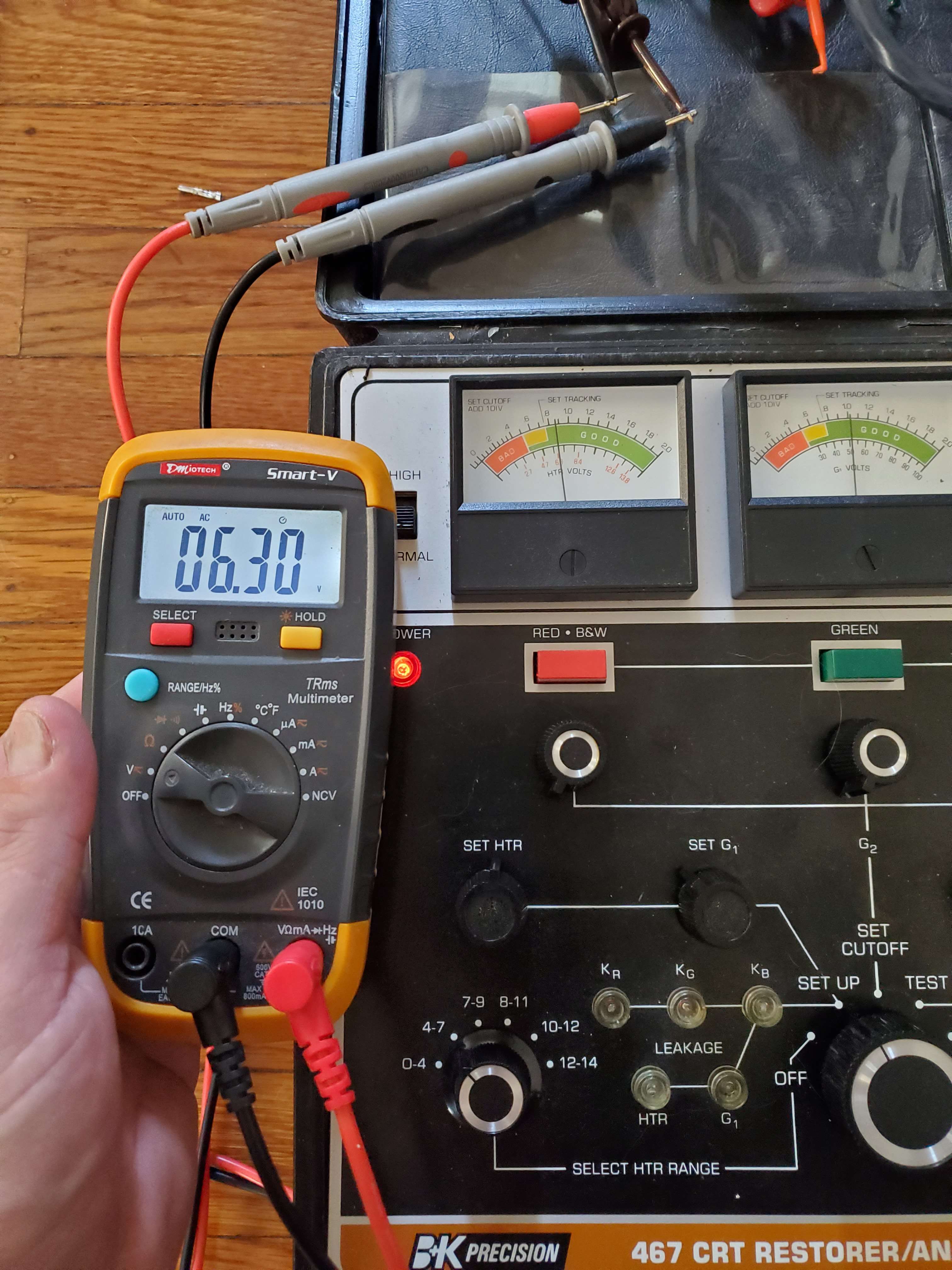
- As a last resort if you want to test the heater voltage without use of any adapters, you can touch the probes of a digital multimeter (in AC voltage mode) to pin 1 and 2 of the tube socket cable. Be very careful when performing this step to not short any pins together - if you do you'll blow the internal fuse or diodes. Pin 1 and 2 can be identified using the pinout below.
Power your tester, turn the function dial to SET-UP, then adjust the heater voltage dial on the tester until your multimeter reads exactly 6.3v. Observe the tester's heater voltage reading on the far left meter (labeled Red B/W). If the meter reading does not match the value displayed on the multimeter you need to adjust the heater voltage meter using potentiometer R16 inside the case until it matches.
Capacitors
To ensure the tester works properly in rejuvenation modes you should check the health of the capacitors. I have not personally seen a single BK 467 with capacitors that didn't need to be replaced - due to their age and the rough conditions they operate under, they don't tend to survive to current day. I have seen fewer examples of 490s that needed their capacitors replaced but if you are serious about having the safest possible rejuvenation conditions with your tester I suggest you replace the capacitors. A capacitor kit can be purchased here.
Here is a list of the suggested capacitors to replace. If you are building your own capacitor kit off Digikey/Mouser, be sure you buy axial style instead of radial for C11 and C12.
- C1 220uf @ 50v
- C2 220uf @ 50v
- C3 220uf @ 50v
- C11 47uf @ 450v (axial)
- C12 47uf @ 450v (axial)
- C13 1000uf @ 25v
- C14 1000uf @ 25v
- C19 10uF @ 250v
- C20 10uF @ 250v
Resistors
The BK 467 (490 unverified) uses a special type of resistor called "carbon composite" that is no longer manufactured due to its loss of accuracy with age. I have not verified if the BK 490 is still using this type of resistor or not. These carbon composite resistors should be replaced with metal film type for the best performance and accuracy of the tester.
- R1 11Mohm 5% 1/4W
- R2 11 Mohm 5% 1/4W
- R3 11 Mohm 5% 1/4W
- R36 11 Mohm 5% 1/4W
- R69 11 Mohm 5% 1/4W
- R37 51 Kohm 5% 1W
- R38 3.3 Kohm 5% 1W
- R39 4.7ohm 10% 1/2W wirewound. replace with same type
- R46 620Kohm 5% 2W
- R47 620Kohm 5% 2W
- R48 620Kohm 5% 2W
- R58 82ohm 5% 1W
- R70 470Kohm 5% 2W
Fuse Replacement
If your tester does not power on when put in SET-UP mode, you should check the fuse. Page 35 of the manual gives instructions for replacement.
Ballast Bulb Replacement
If your rejuvenation bulb does not light (burned out, missing, etc), you can replace it with a 230v 10W S-6 Base bulb.
Socket Adapters
OEM Adapters
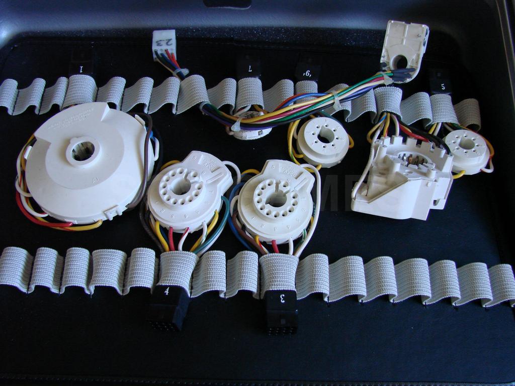
The BK 467 came with six socket adapters packed inside from the factory (numbered 1 through 6 on their connector base - BK part number is the same but with a "CR-" prefix). The BK 490 comes with 23, 24, and 31 (a much more useful set for modern tubes). The top half of the briefcase is a storage pouch for socket adapters and if you are considering buying one, you should check to see if any adapters are included within the pouch. If your tester comes with any adapters other than the aforementioned, they were custom-ordered by the original owner. BK sold 48 different tube socket adapters (CR-1 thru CR-45, followed by CR-70 thru CR-71 and the CR-XA Universal Adapter) - you can see a full list of them in this collection, as well as at the bottom of the "CRT Set-up Chart 1999" PDF.
Adapters CR-1 thru CR-6 that are included with the 467 are not very helpful for modern tubes - they mostly cover pre-1980 color tubes and monochrome tubes. The most common modern tube sockets you will need are CR-23, CR-31, CR-36, CR-71, and CR-40 - some of which are included with the 490.
DIY Adapters
In order to build your own adapter, you will need the following parts:
- 1x Molex connector part # 03-06-1122. You can find these on Digikey, Mouser, and eBay.
- 12x Molex 3.68mm pins part # 0002061101
- Molex crimping tool
- 24 AWG Stranded Wire
- Tube socket - you can either buy these brand-new from an arcade parts supplier, or, if unavailable, salvage them from a donor CRT neckboard
Universal Adapter CR-XA
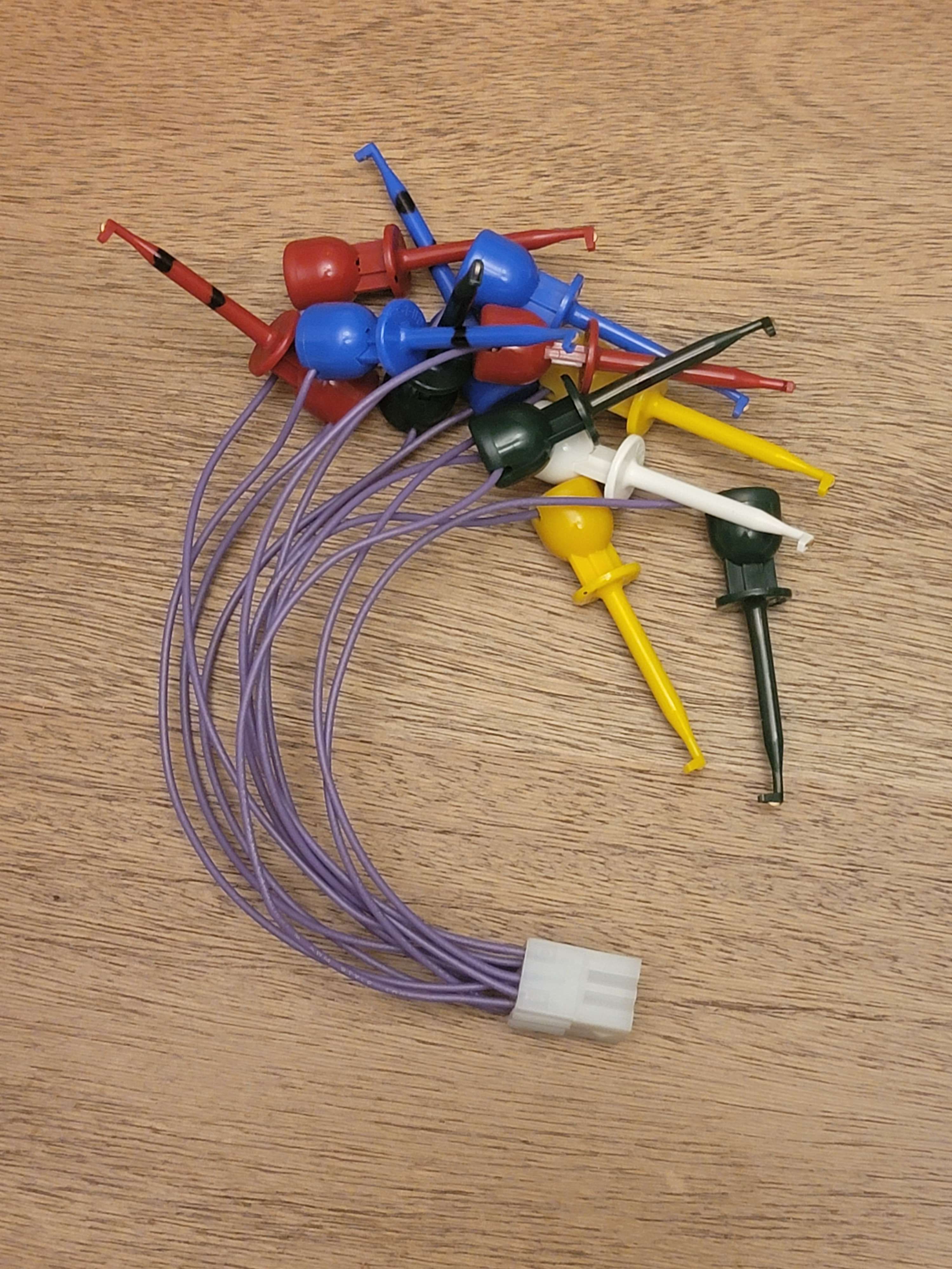
For building an adapter you'll need to buy hooks, the molex socket listed above, and some wire. The best hook to buy for making your own CR-XA is the EZ-Hook XR Mini. If you test a lot of vintage CRTs like pre-1980s where the neck diameters and pins are huge, you might want to get a hook with a larger diameter - the EZ Hook Mini will not be able to grab onto these larger diameter pins. In my case I only test older tubes on occasion, so I run alligator clips from the tube pins to my EZ Hook Minis.
I recommend buying 3 red, 3 green 3 blue, 2 yellow, and 1 white. Each group of 3 same-color hooks will cover each color's K, G1, and G2 (most CRTs only have a single G1 and G2 shared between all 3 colors but you want to equip yourself for all possibilities...), the two yellows will be for heater H1 and H2, and the white will be for Focus (G3) when applicable. Take a sharpie and put a single hashmark on each color's G1, and two hashmarks on each color's G2. Now you know which one is which without having to remember anything :)
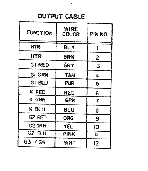
In order to wire the Molex connector properly, refer to the pinout charts listed below. The first image shows the pin numbers for the cable on the tester. The second chart gives a function label for each pin number - for example, pin 1 and 2 are both for the Heater, pin 3 is G1 Red, etc. You should be able to figure out the wiring from this info.
Socket Pinouts