Table of Contents
Safety Warning
CRTs themselves can retain energy for extended periods of time after being powered off. Power Supplies are also known to retain voltage for some time after being unplugged. As an extra precaution, you are advised to wait several hours for this latent energy to discharge before attempting to service your monitor. Alternatively, there are safe ways to expedite this discharge process with proper tools (see below).
Removing the Rear Case / Shell
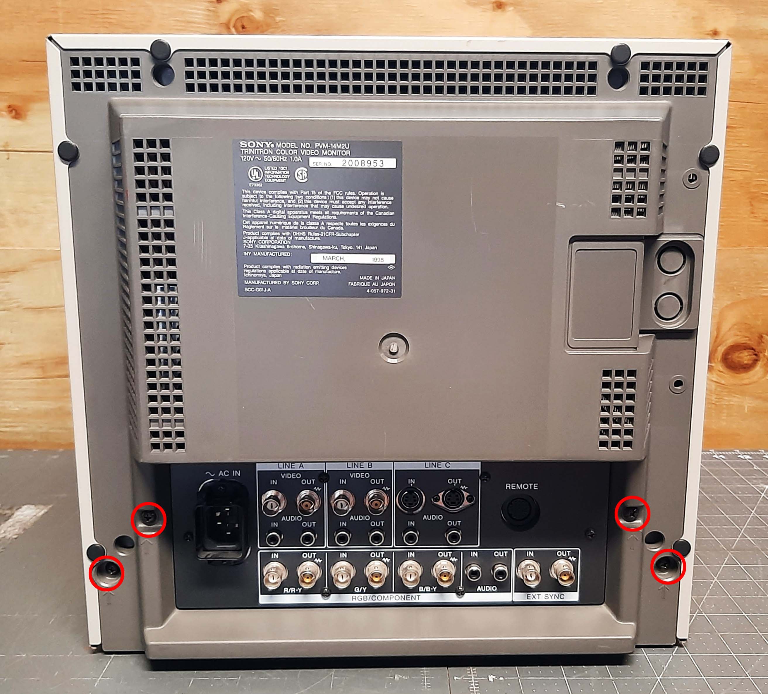
Start by removing the side screws - usually there are six total - three on the left and 3 on the right. Next, remove the rear screws. Usually there are four and they are near the input section, and they are all marked with arrows. DO NOT REMOVE THE PLASTIC RIVETS FROM THE REAR OF THE PVM.
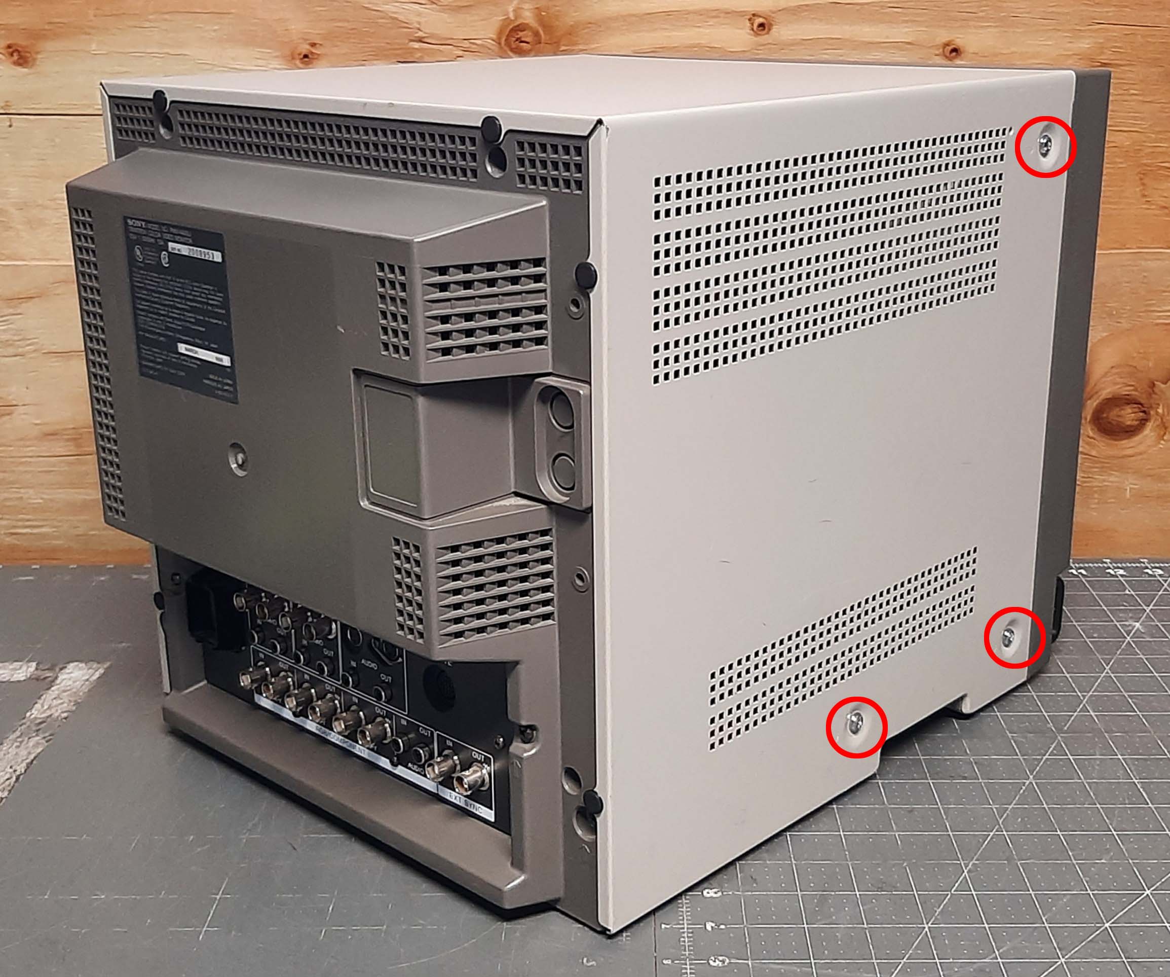
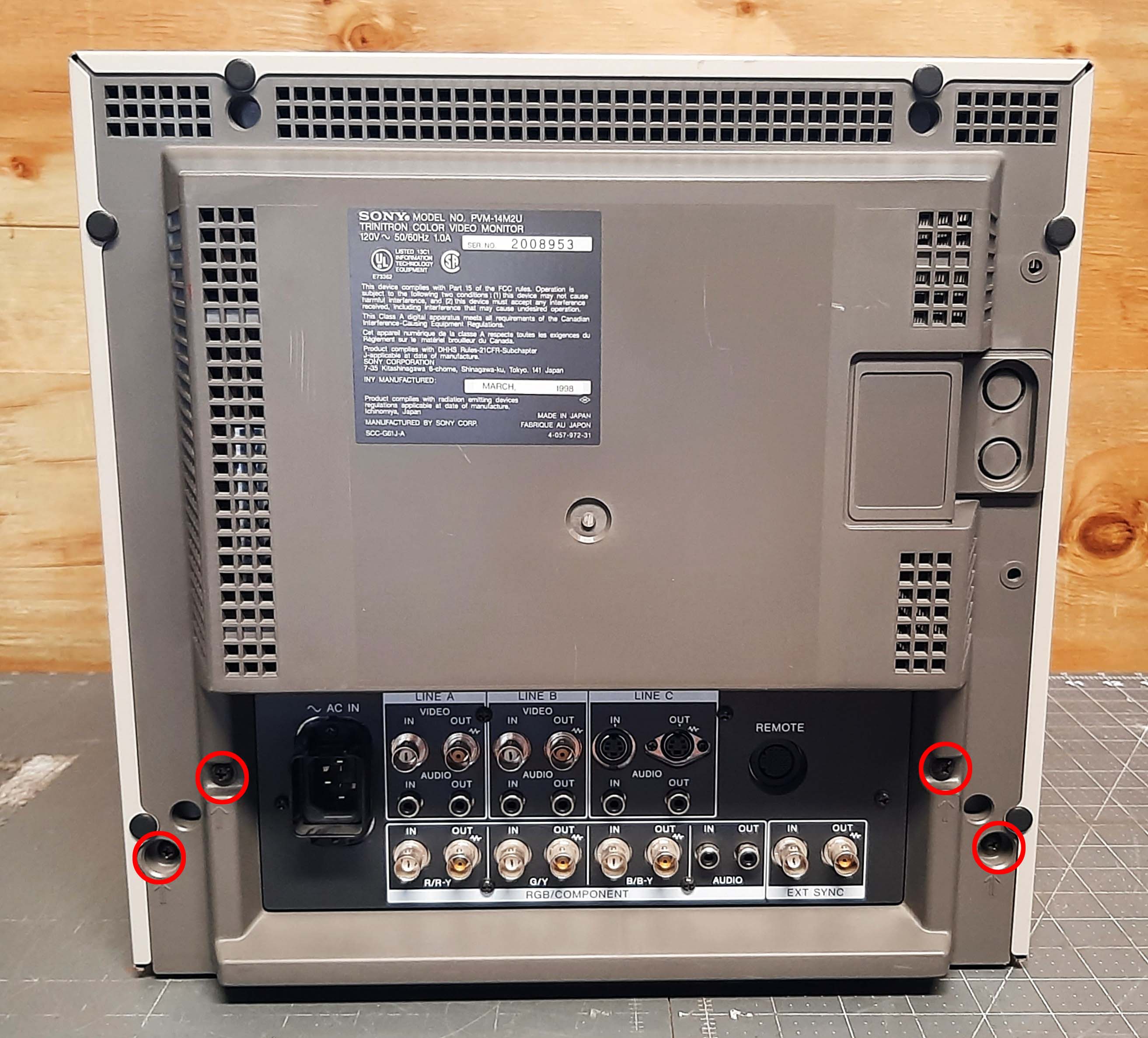
Once you've removed all of the screws (and NOT the plastic rivets!), the case is ready to come off. Sometimes they are stiff/tight, but most should come off easily by first turning the PVM away from you (so you are facing the rear), and then pulling the whole rear shell towards you. Sometimes lifting the PVM a little off the table will help finesse it off. If it refuses to budge, sometimes some strategic palm-whacks along the seam where the plastic bezel meets the metal rear shell will break it loose.
Discharging the CRT
Most Sony PVMs (when working properly) are designed to be self-discharging and do not retain energy in the CRT after being powered off for ~10 seconds. However there are cases where they don't (either due to a fault or it could be an older model which doesn't have automatic discharging), so even an experienced service technician will still take the proper safety precautions and double-check the CRT is discharged before service, using a discharge probe. Any high voltage probe rated for 20kV is safe to use for both measuring a live CRT's high voltage and discharging it. To discharge the CRT with a probe, you simply attach its grounding clip to the CRT's grounding strap or any metal part of the monitor chassis that has continuity with the tube's DAG coating (the black paint on the back of the CRT's glass envelope). Once ground is attached, you slip the tip of the probe under the anode rubber cap until you make contact with the metal conductor at its center. If the CRT had any voltage, you will hear a sizzle or zap as the electricity jumps from the anode to your probe tip, discharging to ground.
If you want to be extra safe, you can buy insulated gloves rated for high voltage (class 0). This is unnecessary but I will mention it here for those that want to take all possible precautions.
A Note on DIY Screwdriver Discharge Tools
There are two main reasons why a proper high voltage probe is recommended for discharging:
- Probes are designed to be physically longer than the arc length of 20kV live voltage, and none of its parts are conductive (other than its tip, obviously). This means your hand can't possibly get electrocuted during any proper use of the tool. Conversely, when you use a screwdriver you must ensure the handle of the screwdriver is completely insulated from the metal shaft of the screwdriver, and you have to be really careful since this conductive metal shaft is leading straight up to a couple inches away from your bare hand. Electricity will travel the whole length of the screwdriver shaft, which brings it much closer in distance to your bare hand than is recommended in safety guidelines.
- Probes contain an internal bleeder resistor to allow the discharge process to happen at a lower current, which is safer both for you and the CRT electronics. Using a screwdriver is like touching a bare wire from the anode to ground. It will instantly zap all the electricity from the tube through the screwdriver to ground. This can be dangerous.
With those two precautions in mind, if you still want to use a screwdriver then be sure to keep your hands away from the metal shaft (ideally wear some insulated gloves of some kind) and use a decently thick wire to connect the screwdriver to ground. Its recommended to use alligator clips (or to solder the wire directly to the shaft, if you have the means to do so). Do not just wrap a bare wire around the screwdriver and expect it to work well or be safe. If you don't have the means or motivation to even make a proper DIY tool for your own safety, you have no business being inside of a high voltage electronic device.
Service Positions
P Board (Power)
The P board can be angled out 45 degrees from the case by changing its mounting point. First you must unmount it from stock position by removing the two screws holding it in place, then lifting the whole bracket upwards to remove it from its retaining tabs. There is a second set of tabs on the flat edge of the P board's plastic bracket to use for reattaching it at a 45 degree angle.
This angle allows for access to some of the components on the top side of the board. If you need even more access, you can remove the metal shield from the P board.
A Board (Video, Deflection)
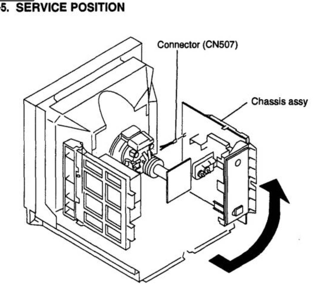
The A board is a bit more difficult to put into service position. The end result will be the board is rotated onto its left side, placed outside of the PVM chassis. This allows for some access to the bottom of the board. and is really the only way to do live diagnostics on these models for things like video signal issues. Some parts will still be obstructed by the plastic bracket, sometimes I cut out sections of the bracket to give better access. You can also remove the bracket but then nothing will be holding the Q board in place and the A board is at higher risk of flexing or shorting out on something conductive.
First you must disconnect the ground plate from the Q (input) board. It is the metal bracket where several ground wires are all meeting together. Remove the bottommost screw to take this bracket off the Q board.
Next you need to remove 3 connectors in the front right-hand side of the A board. One is a black ground wire that clips into place. To unclip it, you must apply pressure to the retainer, which is located on the front side facing away from you. Usually squeezing your finger into the center of the clip is enough to release it. It's ok to bend the connector on the board a little in the process. Next to that ground plug are two more plugs, a large one and a small yellow one. The large one needs to have its plastic retainer squeezed to remove it. The yellow one just pulls straight out.
Next you need to remove the yoke connector. It is the multicolored red/yellow/blue/white plug on the right side of the board near the heatsinks.
Finally you need to remove the two connectors coming from the P board.
Once you've released those 4 connectors and removed the ground plate from the Q board, the A board should be free to slide back. Depending on the model there may be an additional black 4-pin connector in the front left side of the board (hidden under the P board) that needs to be removed. There may also be one ground wire attached to the plate that needs to be unscrewed. Some medical MDU models may have additional ground wires that need to be unscrewed.
Slide the A board back towards you far enough that its free from the sled tracks in the bottom of the chassis. At this point you can start to carefully lift it up starting at the right side, shifting it out of the chassis to the right as pictured below. Now the A board is in service position.
Unfortunately since we had to unplug some wires to do this, the PVM won't power on yet. We need to plug back in all of the wires.
The P board connectors will need to be re-rerouted ABOVE and over the top of the P board and back down towards the A board where they plug in.
The other connectors we removed go the front panel - if you look deep into the front of the PVM you'll see some retaining clips holding extra length for this wire harness. Untwist the clips to release the extra wire length, then plug these back in. Lastly I suggest using an allgator clip wire to reconnect the ground wire to its place on the A board - since it is not physically long enough to reach otherwise. I do not know why the service manual depicts it as long enough - in my experience it doesn't reach.
 This work is licensed under a