Fan Mod - Ikegami TM20-80R
In this article we are covering different approaches that can be used to add a fan to a crt monitor. Several monitors tend to run pretty hot, and that has an negative impact on the overall life of the monitor: components like electrolytic capacitors are sensitive to heat and will degrade and age much faster.
Examples of monitors that have this problem are some Sony BMVs and PVMs (with the excellent case of the PVM-14L5), the Ikegami TM/HTM family (especially the 9" and 14") and several others.
An effective way to lower the internal temperature is to force air flow by installing a small fan. Usually the best strategy is to have the fan installed near or above the hottest components and oriented such that it will push the hot air out.
Any side effects? unfortunately yes: electric motors tend to create electromagnetic interference, that gets propagated back to the monitor through the power rail used to power the fan.
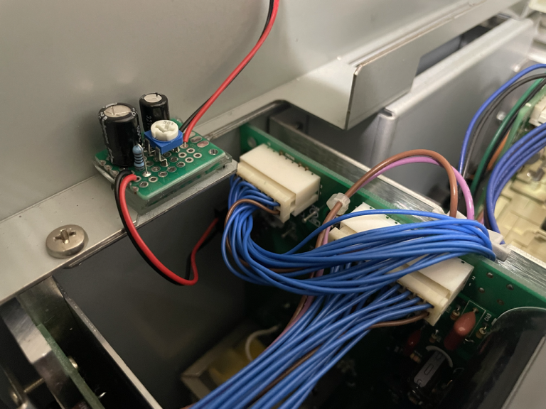
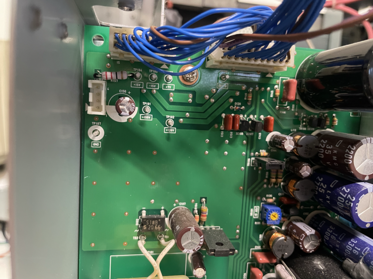
To understand the problem let's have a look at the effect of adding a Noctua 40mm fan to an Ikegami TM20-80R. Many ikegami monitors have connectors that expose the 15V rail, and the TM20-80R is no exception: connector CN911 has GND on pin1 and 15V on pin3.
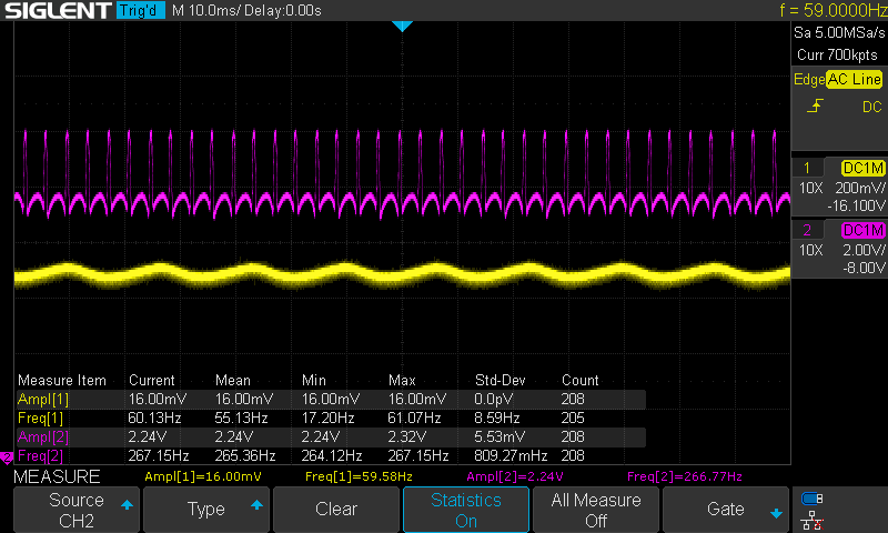
Without anything connected, the 15V signal looks like the following:
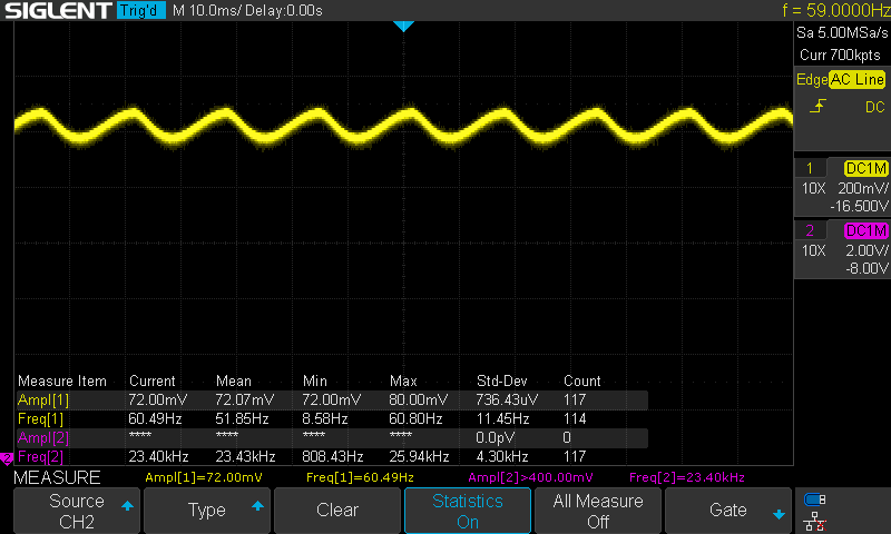
and you can clearly see how the capacitor in the rectifier is charging/discharging at 60Hz, which is the frequency of the line AC power. In the picture above the DC value is around 16.5V (with no load) and the amplitude of the oscillations around 70 mV.
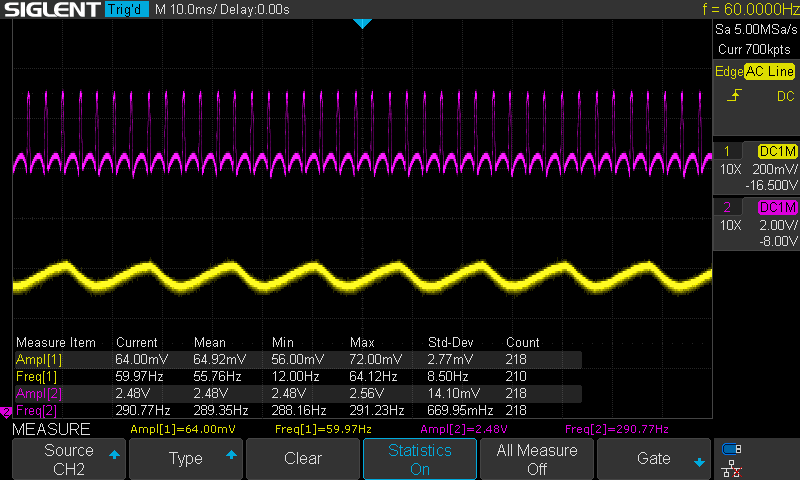
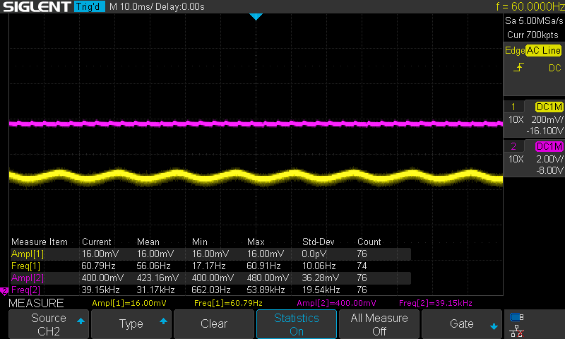
Installing a fan in series to a 200 Ohm resistor (to slightly lower the voltage and make the fan run quieter) changes the waveform to the following:
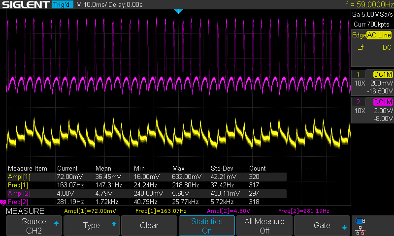
In the picture the yellow signal is the voltage measured at the connector, and the purple is the voltage measured at the fan. Notice the following:
- the fan motor introduces very big 4.8V spikes, at an average frequency of 140 Hz (purple signal)
- those spikes are propagated back to the input (yellow signal), and from there potentially to any component connected to the same rail
Is that bad? well it depends by how well the rest of the circuits in the monitor are designed and how sensitive the other components are. The possible side effect is noise in the image.
So what can we do? well, I can think of a few options...
- Do nothing. The monitor might be doing a good enough job at filtering that out and the noise might not be present or noticeable
- Use an external power supply for the fan, like a wall wart. In this case the fan is not part of the same circuit so no interference; it will have to be manually turned on/off though.
- Add some specific circuit to filter out those spikes
In the rest of the article we will explore option 3.
Passive circuit with filters
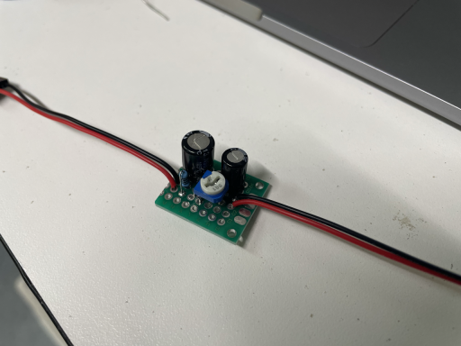
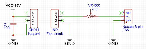
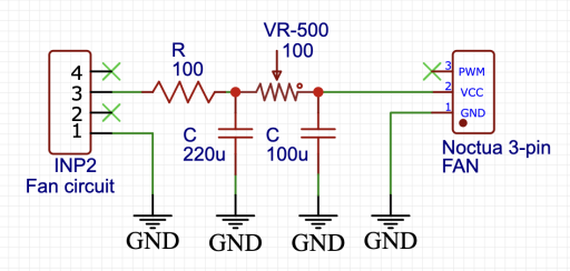
The most simple circuit is just a variable resistor that is used to tune the voltage to the fan motor; this is needed to make sure the fan is powered with the right voltage and to regulate the fan speed (useful to let it run more silent). In my case I used a 500 Ohm potentiomenter, tuned to have approximately 200 Omh resistance in the circuit.
The output of this circuit is the one shown in the previous image, with the 140 Hz spikes.
A simple way to filter some of the noise is to add a low pass filter; this can be implemented with a RC network, and I used R=100 Ohm and C=220 uF to achieve a cutoff frequency around 7.5 Hz, well below the 140 Hz we want to get rid of. Since we now have an additional 100 Ohm in the circuit, the variable resistor has been tuned down from 200 to 100 Ohm, to keep the total load consistent.

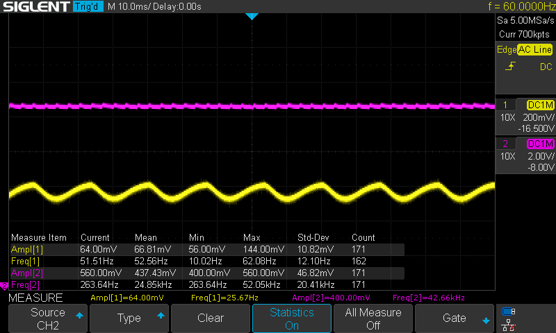
The result is the one shown in the picture below:
Results are pretty good:
- spikes in the input (yellow) are gone
- spikes in the output (purple) have been reduced from 4.8V to 2.5V
With this circuit there is essentially no visible noise propagated back to the 15V power rail. Good!
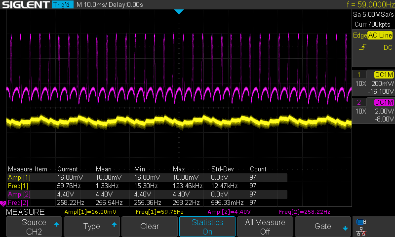
But we can do better and add another filtering stage. It's as simple as adding another RC pair, and I chose to add a 100 uF capacitor after the variable resistor, that with the our values had a cutoff frequency around 15 Hz.
Cascading the 2 RC filters has a multiplicative effect that is visible in the following picture:
- no spikes in the input (yellow)
- almost no spikes in the output (purple): they now are ~500 mV, 10X smaller than the original value.
Considering we used just 2 resistors and 2 capacitors, the result is quite good!
Using a buck converter
In case there is no power rail with a compatible voltage for your fan, one option is to use a buck converter, that is a circuit that can step down the voltage to the required value. The advantage of using a converter instead of a voltage divider is much higher efficiency (>90%); the linked Wikipedia page is quite comprehensive. If you need to step the voltage up you can use a boost converter or even a buck-boost converter if you want a single device that can step up and down as needed.
Beside adding the converter, the theory is the same.
With just the buck converter:
Adding 1 stage of RC filtering:
Adding the second stage of RC filtering:
In this case the input voltage has smaller oscillations because the buck converter I used came with an additional 220 uF filter capacitor at the input.
Mod on the Ikegami TM20-80R
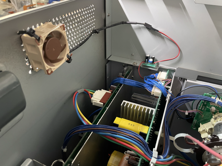
For my monitor I chose to go with the 2-stage passive circuit, and use the 15V power rail to feed a 40mm Noctua NF-A4x10 FLX fan. I tuned the variable resistor to provide ~9.5V to the fan, that makes it very silent while still producing a good air flow.
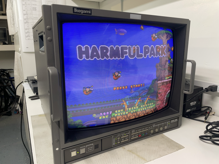
Closing with a few pictures of the monitor: