
Table of Contents
Overview

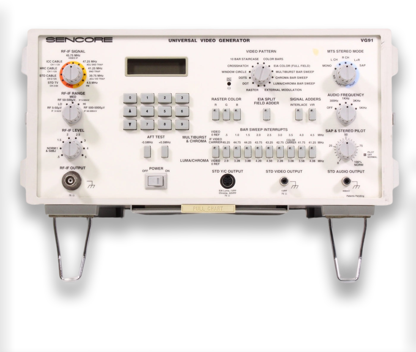
The Sencore VG91 Universal Video Generator is a test pattern generator with RF, IF, Composite, and S-Video output capabilities. It can be linked together with other equipment like the TV92 TV Video Analyzer or the VC93 VCR Analyzer, where it is used to provide video/sync during other diagnostic tests.
It is very useful for diagnosing tuner problems in any CRT that uses 45.75 Mhz IF, which eventually became the standard for all modern NTSC CRTs.
The owner's manual is extremely detailed and provides a lot of teaching and guidance on NTSC video signals and how to best utilize the Sencore VG91. I recommend reading it before using the unit.
Key Features
- All Channel TV-RF Generator For Complete Tuner Analyzing that simulates any "off air" or cable channel to completely analyze all tuners. Fully modulated with video and MTS audio signals with a wide range attenuator for simulating weak or strong signal levels.
- Variable Level 45.75 Mhz Video-IF Troubleshooting and Alignment Generator that isolates problems to the tuner or IF stage, permits easy AFT alignment, and allows for IF trap setting using patented IF signals.
- Exclusive and Dynamic NTSC Video Test Signals for complete analyzing of IF, luminance, and chroma circuits.
- Proof-Positive test for MTS Stereo / SAP on All-Channels. Four stereo modes and audio test tones ensure complete performance tests and alignments.
- Standard Y/C (S-Video), Composite Video, and Audio Line Output for quick and reliable testing of all standard NTSC video equipment.
- Spare Video Output and Exclusive Interconnect Design that Permits Future Updates or Expansion. Add the TVA92 to increase your TV analyzing capabilities and the VC-93 All-Format VCR Analyzer for exclusive VCR playback and record troubleshooting.
- Portable and Easy-To-Use. Use the VG91 in the shop or in the field - take it with you wherever you analyze video.
Buyer's Guide
Most sellers don't test these, and if they do, usually only test the Composite output. Beware that a working composite output does not guarantee the RF/IF output is working correctly.
Included Accessories
- RF IF TEST CABLE (380301) provides 75 ohm BNC to quick-connect F connecter cable for use with RF-IF Output Jack
- S-Video Y/C CABLE (395270) provides a 4 pin miniature jack male to 4 pin miniature male for use with the STD Y/C OUTPUT Jack
- VIDEO TEST CABLE (39B296) provides a 75 ohm RCA phono to RCA phono cable for use with the STD VIDEO OUTPUT Jack
- AUDIO TEST CABLE (393241:A) provides a RCA phono to RCA phono cable for use with the STD AUDIO OUTPUT Jack
- R-IF TROUBLESHOOTING BALUN (89A302) provides 75 to 300 ohms matching transformer with 100 DC blocking secondary for use with IF TEST CABLE when Injecting signals into tuner or IF stages.
- F TO RCA FEMALE ADAPTER CABLE (39A181:A) Short adapter cable "F" to RCA Female to connect RF-IF TEST CABLE to tuner or chassis.
- F TO RCA MALE ADAPTER CABLE (39A162:A) Short adapter cable "F to RCA male to connect RF-IF TEST CABLE to tuner or chassis.
Optional Accessories
- BNC Cable (39G232) - BNC to BNC cable for use with rear panel jacks.
- SYNCHRONIZING INTERCONNECT CABLE (39G266) - Provides a connection between the SYNCHRONIZING SIGNAL OUTPUT Jack and the Sencore companion analyzers or expanding accessories (TVA92, etc).
- RF-IF Matching Balun (39G72) - Provides 75 to 300 ohms matching transformer with DC blocking secondary for use with RF-IF TEST CABLE for connecting to rear antenna terminals or chassis.
- IB72 IEEE 488 BUS Interface Accessory - connects between the INTERFACE ACCESSORY Jack and the IEE port of a bus controller to allow the VG91 to be used on an IEEE system.
- IB78 RS232 Interface Accessory - connects between the INTERFACE ACCESSORY Jack and the IEE port of a bus controller to allow the VG91 to be used on an RS232 serial system for automated testing.
- PC259 Front Panel Protection Cover
Manuals
- Owner's Manual
- Quick Start Guide (located on the underneath of the unit, pull out to view - scan coming soon).
- Sencore Tech Tip 214 - Learning to use the VG91
- Factory Calibration Guide (not recommended to try this unless you can confirm yours has bad calibration with no circuit faults)
- Sales Brochure
- Power Supply Schematic (confirmed to exist but not available online - please send a link if you have it).
Common Problems
No Video Output
See "No "Relay Click" on Power-up".
Weak RF Output
It is possbile some capacitors on the RF/IF board inside have gone bad. Replace C141, C158, and C189 - all of which are near the P12 connector to the RF/IF tuner. Also try cleaning the whole RF/IF board with a toothbrush and 99% IPA. If this doesn't help, see No "Relay Click" on Power-up below.
No LCD Backlight
There is a potentiometer inside on the rear of the front control panel PCB (just a small pass-through hole for a screwdriver). It seems many of these had the backlight turned down at the factory. If your backlight is weak, continue reading No "Relay Click" on Power-up below.
No "Relay Click" on Power-up
All of the above issues can be related to the power supply inside. The power board has capacitors that are known to fail prematurely, and when they fail they leak corrosive and conductive electrolytic fluid all over the board. See the Capacitor Replacement section below for more information.
Once you have ruled out capacitors, you should check the power output rails to see if any are missing. The rainbow connector on the side closest to the front of the unit is the output connector. With respect to ground, each pin should measure as follows: GND | +30v | -15v | +15v | -5v | +5v | 8v (unregulated)
If you are missing one or more power outputs, the likely failure point is the corresponding adjustable output linear voltage regulator(s). there are 5 of them - 2x LM337T (or NTE957) and 3x LM317T (or NTE956). Four of them are on the power PCB and the last one is mounted nearby on the side wall of the VG91 case. If you can't find original replacements, the NTE equivalent parts are NTE957 and NTE956, respectively.
If your backlight is still dim after fixing the power supply, it may just need to be turned up to a brighter setting. You can adjust it using a potentiometer located behind it, inside the unit. Make sure to use a nonconductive screwdriver, or perform this adjustment while the unit is powered OFF.
Maintenance
Capacitor Replacement
Even if your unit is working fine, you should open it up and recap the power supply. The capacitors are a known failure point and can cause damage to the board. To fully recap the power supply you need:
- 5x 220uF 50v capacitors (original spec is 35v but this is too close to the operating voltage and should be increased) - 5mm lead spacing
- 5x 2200uF 50v capacitors (same increase recommendation as above) - 10mm lead spacing
- 1x 1000uF 160v capacitor (200v or higher is also fine, whatever is in stock) - 10mm lead spacing
The PCB is not very high quality and you may have a difficult time getting good heat transfer while trying to remove the old capacitors. You must be careful not to damage the board, it is possible to rip out the plating in the through-holes and cause breaks in the circuit unintentionally. If a previously-working unit does not work properly after a recap, you should check continutity on all of the pads you touched. The board has traces on both sides, so remember to check both sides of the board.