KV-9PT20/40 S-Video Mod
-
The Chroma pin on the LA7672 jungle chip is wired to both the Chroma buffer (which grabs Chroma from the Composite video signal) and the Color control knob. In order for the Chroma input of the chip to function, it must be wired to both a Chroma input and a Color control circuit. You can't just inject Chroma by itself into it.
-
There's a trap filter on the Luma side of the buffer circuit that can reduce the image resolution by filtering out the 3.58 MHz band of the signal. For the S-Video mod, you would ideally want to remove that filter and wire it to a switch so that it's only active when the set is in Composite mode.
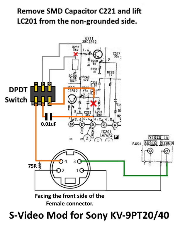
With those details out of the way, here's a successful mod circuit for this chassis:


The gist of it:
-
Remove the SMD 0.01 uF coupling capacitor (C221) between the Chroma buffer circuit and the Chroma pin (36) of the LA7672 jungle chip, this will disconnect the Composite/RF Chroma signal from the chip while preserving the required Color control circuit.
-
Remove LC201 from the Luma circuit (either lift it out of the pin connected to R252 or remove it and locate it elsewhere on the board with one leg connected to Ground) and wire it to the Composite video side on the first pole of a DPDT switch. The original pad where LC301 used to be connected should go to the center leg of your switch and the lifted leg of LC301 should go to the right leg of the switch.
-
Connect the Chroma pin (36) of the jungle chip to the center leg on the second pole of your switch through a 0.01uF ceramic capacitor, connect the Chroma pin of your S-Video connector to the left leg of the switch and connect the Chroma buffer circuit to the right leg of the switch. You should place a 75 ohm grounding resistor on the Chroma pin of your S-Video connector, as the colors will look off without it.
-
Luma should be connected to the Composite Video input pin and the Ground pins of your S-Video connector should go to a nearby Ground on the chassis (One of the Ground pins of the RCA jacks on the back of the set should be a perfect spot).
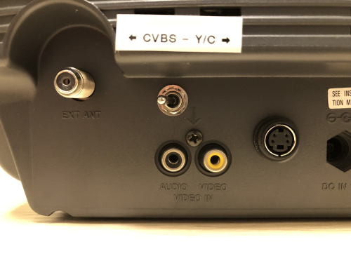
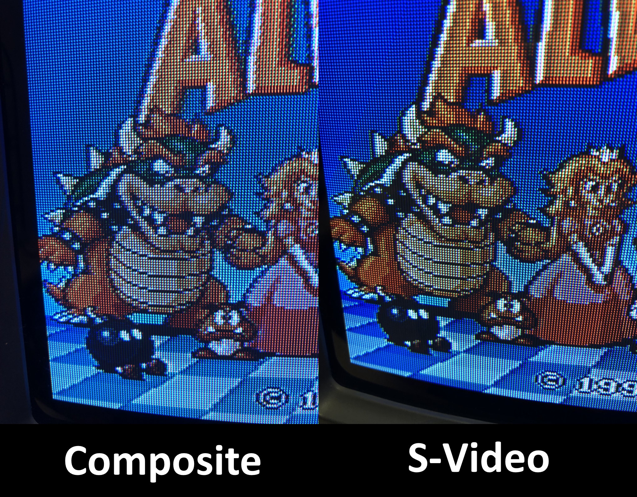
If done correctly, you should get a nice clear vibrant image on your 9" Trinitron when your switch is in S-Video mode and you have a device plugged into the S-Video input.


 This work is licensed under a