Summary
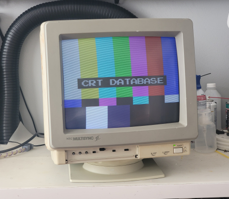
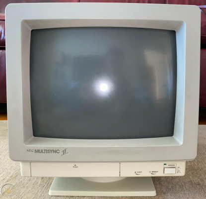
Known as the "Multisync II". Successor to the NEC Multisync I
Noteworthy changes include slightly larger viewable size (due to a more modern tube and shallower bezel), simplification of internal design (which makes it easier to work on), and omission of the stupid analog/digital switch from the Multisync 1 that was prone to killing the input card when positioned incorrectly.
Manuals
- Service Manual - if you need a more legible version of the power supply schematic you can look at the JC-1401 power supply schematic. It's ALMOST the exact same and the scan quality is much better. Watch out for slightly different resistor values.
Media & Promo Materials
Notes
Power Troubleshooting Steps
The service manual has many useful troubleshooting trees. If you have no power or power but no raster, I recommend starting off with these steps:
- Remove the power supply board by removing the two locking screws, unplugging the four connectors, and then sliding the board straight up out of the chassis.
- Turn the monitor onto its right side, stand the power supply up next to the yoke and plug all four connectors back into the power supply. The point of this is to expose the bottom of the PSU so that you can probe it with a multimeter. Make sure nothing is touching where it shouldn't be, make sure nothing is touching the yoke, the anode cap, etc.
- Check the the voltage between C1 and C3 with the monitor powered on. If you get less than 40v you have a failure on at least one half of the PSU and should follow the troubleshooting tree in the manual.
- Check the voltage between K1 and K3. If you have less than 85v you have a totally bad power supply and need to follow the troubleshooting tree in the service manual.
Troubleshooting the STK7404 (IC602) in the Power Supply
This chip is an all-in-one package IC that handles the variable rectification and regulation of the supply to the horizontal output stage. Its operation is crucial to the operation of the monitor and if its not working perfectly then you may have one of the following issues:
- Monitor starts up fine but won't start up again if shut off. This may last for several hours or days before you can start up the monitor again.
- Monitor has no high voltage or only briefly has high voltage before the CRT starts making a discharge noise. Power light will remain on and you will hear an oscillation noise from the power supply but it will not sound like 15Khz and be quieter than normal operation of the monitor
- Blown resistors near IC602 - either went open or are visibly scorched. Replacing them just causes them to blow again, violently. If you have this problem then pin 14 and 16 (the last two pins) are shorted, the boost transistor inside is shorted, and its sending 160v down a 10v line. Discard this bad IC, replace all blown resistors, check all nearby components for operation before replacing with a good STK7404.
All of these issues point to a bad STK7404. You can replace it with another STK7404 (or the 105°C equivalent STK7404H or STK7404-105, it goes by both names). It may also be possible to replace it with an STK7406 but I have not tested this yet.
General Maintenance Advice
Even if you have a perfectly working example of this monitor I suggest replacing most of the caps, starting with the power supply. Most of the PSU caps will be leaking, including the 3 large 100uF 160v filter caps that are epoxied to the board. Once you've recapped the PSU, make sure things are still working and then move on to the main board. The main board caps are important, especially all of the ones near the flyback. I had startup problems even with a fully recapped PSU until I replaced the large 100uF 160v filter cap and 1000uF 50v cap near the flyback. You can probably ignore the caps on the video/input boards in the rear, I haven't had to recap those on mine yet. Just check them for leakage and ESR.
Spare Parts
The 1401 and 1402 share the following major parts:
- Power Supply
- Yoke
- Flyback
Sync
For RGsB (Sync on Green), the monitor will accept sync from the green video signal at the standard of 0.3-0.6vpp. For all other cases (HV Sync, CSync), it needs TTL level to pin 4 (and 5 for V Sync) of the DB9 connector.
Horizontal Output Transistor (2SC3486) Notes
This horizontal output transformer is used across all four of the multisync NEC JC-140X models. I've had to deal with several ones which are dead, so I wanted to include some notes about how to tell if yours is dead.
A "probably good" 2SC3486 will have the following measurements from a multimeter in resistance mode:
- 340-370K with red probe on base and black probe on emitter
- "OL" out-of-range with red probe on emitter and black probe on collector. If you get a reading of 50M or less resistance, the internal diode is bad, regardless of what diode check shows you. This was consistent across all 4 dead 2SC3486's I've replaced.
A "probably good" 2SC3486 will have the following measurements from a multimeter in diode-check mode:
- beep/good with black probe on collector, red probe on base
- beep/good with black probe on emitter, red probe on base.
- all other combinations of the legs should not show any voltage reading or good beeps on the multimeter.
Be careful to make sure the paper guard behind the 2SC3486 remains in place when replacing one. If the back plate of the chip makes direct metal to metal contact with the heat sink its mounted to, it will arc and kill the chip when powered.
DB9 Pinout
MultiSync                VGA
9 Pin D-sub 15 Pin Mini D-sub- Red <------------------> 1
- Green <----------------> 2
- Blue <------------------> 3
- H Sync/CSync <-------> 13
- V Sync <---------------> 14
- <-----------------------> GND
- <-----------------------> GND/NC
- <-----------------------> GND/NC
- <-----------------------> GND/NC
Gallery

 This work is licensed under a