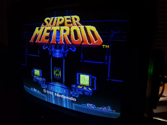
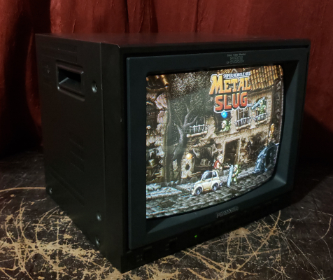
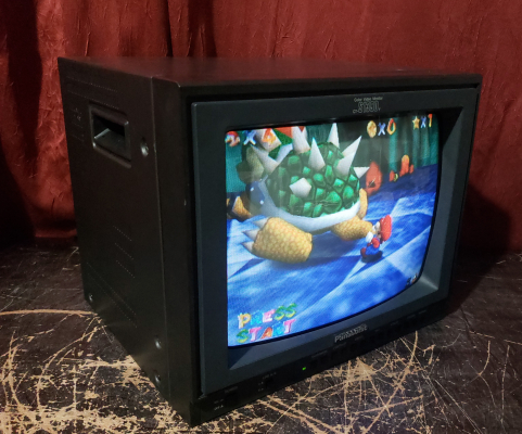
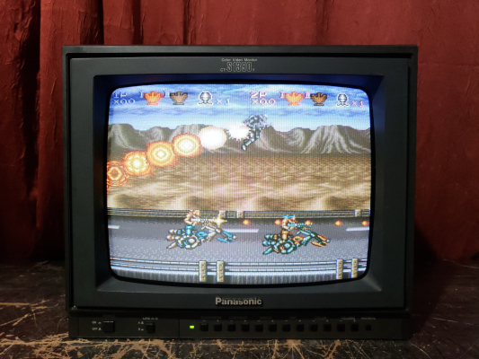
Panasonic CT-S1390Y

Andy King
September 4, 2024, 2:46 am
October 2, 2024, 5:49 pm

Summary

A CCTV Monitor with good TVL for its size (420). RGB Mod is possible but sort of a pain because it needs to be amplified with a THS3714 (see instructions below). The perfect method of RGB modding this TV is still under dispute/development by several people and will be updated if a better method is presented in the future. At this time I do not personally reccomend investing time or money in this RGB Mod because it doesnt have consistent color levels across multiple input sources. I unfortunately did not discover this problem until after finishing my project.

Literature

Notes

Press "Color Up" and "Sharpness Up" simultaneously for 2 seconds to activate the service menu for sub adjustments and h-position. If you get stuck with the service menu displayed even after power cycling the monitor, press "Color Up" and "Brightness Up" simultaneously for 2 seconds to activate the self-test mode and then turn off the monitor. This is the only way I could figure out a way out of the service menu being stuck.

RGB Mod (OSD Mux) Instructions

This monitor has an RGB OSD line wired up for the service menu display. We can use this line to inject our own external analog RGB signal while still retaining the service menu OSD display for all inputs. For your convience I have designed an amplifier board to make this process as simple as possible and it can be printed from OshPark using the link below.

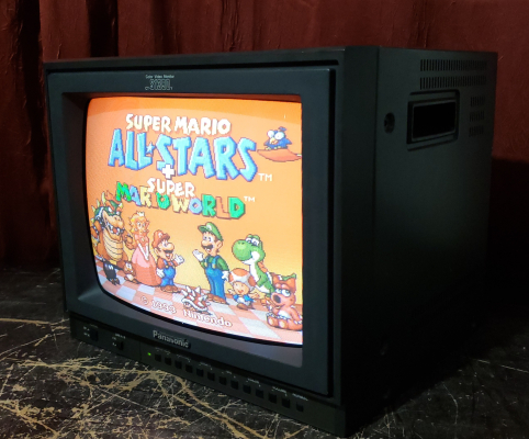
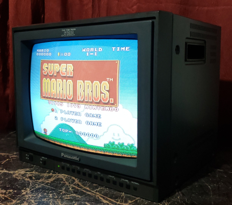
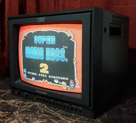
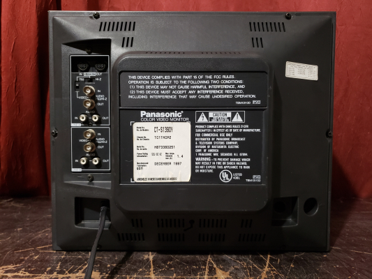
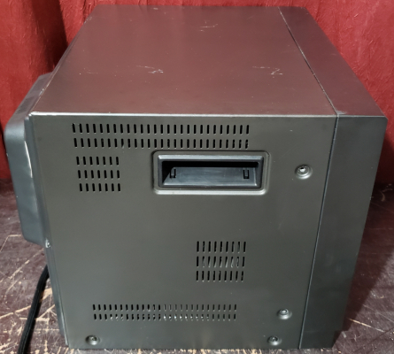
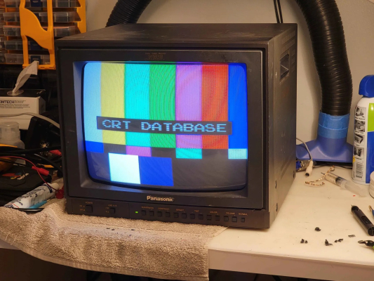
You can see a picture of the RGB input working at the bottom of the page, as well as pictures of the exterior and interior work that was done.

Required Parts:

  • 1x of my RGB Amplifier board from OshPark (or you can make your own on proto board with this schematic). OshPark has a minimum order quanity of 3.
  • Everything in this Mouser cart (I suggest adding 3x 470ohm resistors unless you have a collection of resistors at home. This mod requires some trial and error)
  • 1x panel-mount SCART female connector + mounting screws. Ninigi is one brand that still makes them but there are several others. I got mine from Console5.com. I would avoid getting a right-angle connector because it will be hard to solder to and put angle stress on the wires.
  • 3x diodes (any type). They are NOT in the mouser cart so find some.

Optional Parts:

  • 2x female RCA jacks for audio breakout from SCART input (I got mine from Console5.com.
  • 1x DPDT On-On toggle switch for internal/breakout audio switching (I used this one.)
  • 1K resistors to mix the SCART stereo input down to mono for the monitor's internal speaker

Optional Tools (These will come in handy for future projects too!)

We will be working with these two chips on the board:

  • Microcomputer IC001
  • Chroma Chip IC301

Board modifications

Replacing Resistors with Diodes

Remove the existing inline resistors on the OSD RGB signal lines: R040, 041, and R042. Replace these with diodes, stripe facing away from IC001, so that the color signal can only flow away from IC001 towards IC301, and not vise-versa_. You can verify your work with a multimeter if you have a diode test mode. The diodes are necessary because IC001 pulls the OSD line to ground pretty hard and will make it very difficult to get proper signal levels from our amp later. Any normal diodes will work, I used some I pulled off of a dead Playstation while I was protoyping the amp board.

Power & Ground for the Amp Board

Add a power wire from pin 1 (8v) of IC003. This is a voltage regulator that is located in the middle of the board, near a large rectanguar blue covered capacitor. The 8v will be used to power our own step-down regulator to get 5v to the THS3714 amplifier we are adding. If you're wondering why we didn't just hook up to a 5v source that already exists in the CRT board, I tried that first and there is not enough amperage left to power anything additional. The CRT had trouble powering IC001 and would shut off intermittently.

Add a ground wire from anywhere nearby that is ground. I forget which pin of IC003 is ground but you can use that if you want.

The 8v power wire goes to the 8v input of the amp board. The ground wire goes to the ground input of the amp board.

On the other end of these wires I suggest adding some type of quick-disconnect so that you can easily disassemble the monitor without pulling on your wires and having it look like a mess. My Amp Board is designed to have male Duponnt-spaced connector headers on it.

Input wires for RGB to IC003

You must solder a wire for R, G, B, and Blanking input to the signal-end of 4 resistors on the OSD line. R044 is for Red, R045 is for Green, and R047 is for Blue. R046 is the blanking line. Check out the image gallery below for pictures of the mod.

If you don't know which side of the resistor is the signal side, its the one that isn't going to ground. Shine a flashlight from behind the circuitboard and you will be able to see the signal trace going in one side of the resitor hole and back out the other. This is the signal trace going from IC001 to IC301. The other side of the resistor will have a trace leading to the thick ground plane in the board. You can verify the ground-end using a multimeter.

Again I suggest adding a quick-disconnect female connector to these wires.

Connections to the amp board

Solder the following wires from the SCART connector to the amp board + CRT. Again use quick disconnects wherever you can and try to group them together to make them stronger and less easy to come apart by accident.

SCART Pinout Overview:

  • 15 (R) -> R input of amp board
  • 11 (G) -> R input of amp board
  • 7 (B) -> R input of amp board
  • 16 (Blanking) -> R046 resistor (signal side) on CRT mainboard.
  • 17,18,21 (Signal GND) -> any ground point in the chassis (for example composite's ground on pin 7 of the input board? you decide)
  • 2 (Audio L) -> 1K resistor (optional) -> Audio input on the CRT input board. If you are doing the optional DPDT switching for external audio out then see below before connecting. Make sure you are using the audio input that matches what input you chose for sync.
  • 6 (Audio R) (Optional) -> 1K resistor (optional, otherwise don't connect at all) -> Audio input on the CRT input board. If you are doing the optional DPDT for switching then see below before connecting.
  • 4 (Audio GND) -> Audio L ground on the CRT input board.
  • 20 (Composite Sync) -> S-Video input pin on the CRT input board (pin 3). I tried using the composite input but luma sync from my N64 didn't work in that pin. If you get a jumping picture from your source, switch the impediance from 75ohm to HIGH on the back of the monitor.

At this point every input and output pin of the amp board should be connected to something in the CRT or your SCART harness if you did everything correctly. Go ahead and hook up a SCART RGB source and fire up the CRT. Make sure its on the input you chose for connecting to pin 20 of the SCART plug.

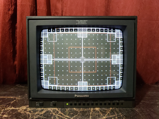
Generally speaking the GAIN pots should be turned all the way up to the brightest in almost all cases. If having the GAIN turned up is too intense, your CRT is more than likely not calibrated properly. Unplug the SCART connector, plug in S-Video or composite 240p test suite and calibrate the monitor before continuing.

Next hook RGB back up and adjust the BIAS pots until you get a nice cutoff for all 3 colors. This adjustment procedure is the same as any other CRT adjustment, documentation is on this website if you don't know what a good cutoff looks like.

If after adjusting the monitor properly for S-video input you find that one of the colors is still brigher than the rest in RGB with proper cutoff, you can go ahead and use the gain adjustment pots.

Optional Audio Circuit

Here is a schematic for how to use the optional audio parts mentioned previously. This circuit does proper stereo to mono mixdown of the SCART stereo input for the internal mono speaker. It also allows you to flip a toggle switch to direct the SCART stereo audio to two RCA audio outputs instead of the internal speaker, esentially functioning as a built-in audio breakout cable for your SCART input.

Audio Circuit

Videos

Gallery

Panasonic CT-S1390Y Panasonic CT-S1390Y Panasonic CT-S1390Y Panasonic CT-S1390Y Panasonic CT-S1390Y Panasonic CT-S1390Y