Sony KV-13M10
September 8, 2024, 2:19 am
June 24, 2025, 6:25 pm
Summary
Very similar to the earlier KV-13TR28, the 13M10 shares the same tube and case design, but uses a simplified chassis design with fewer features and adjustment options.
Manuals
Media & Promo Materials
Notes
Trinitrons using tha BA-1 and BA-2 chassis are capable of syncing to 50 Hz. To enable this, enter the service menu and set VSMO to 1. PAL video will still be in black and white if you use the composite inputs, but can be displayed in color via an RGB mod.
With the BA-2 chassis, Sony began simplifying their chassis design and, in the process removed features that were present in previous generations. Most notably, these TVs no longer have an H Stat pot on the neck board to regulate horizontal convergence. While the tubes used in the 13" models still have the necessary internal resistor, the convergence voltage pin is grounded and all adjustments must be done using the neck rings.
RGB Mod
Written by Matt Ross (6tanks)
Like the previous BA-1 models, BA-2 chassis Trinitrons have a secondary set of RGB input pins on the jungle chip. These can be used to add RGB capability without affecting the OSD.
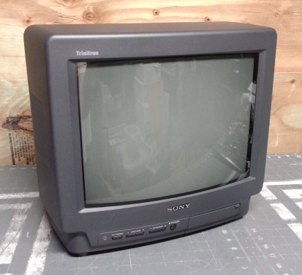
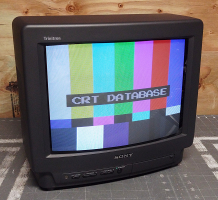
The TV pictured in this guide is a KV-13M10. It should also apply to the 20" BA-2 Trinitrons: KV-20M10 and KV-20S10.
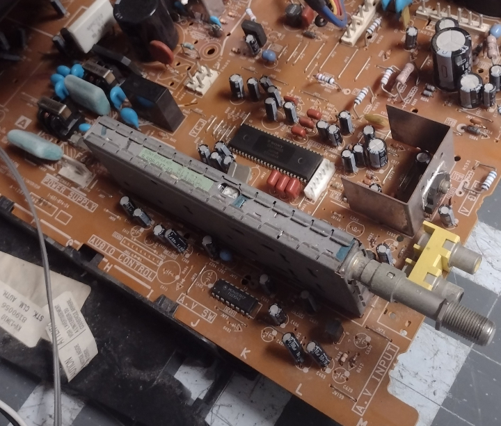
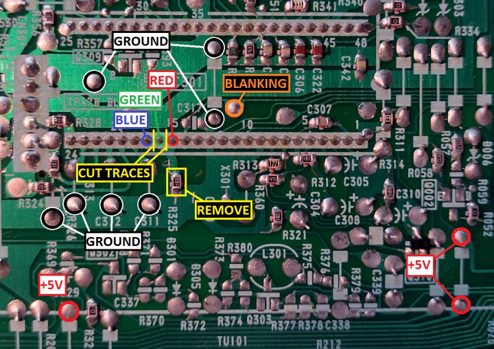
On these TVs, the jungle chip (IC 301) is located on the A board near the tuner. Most of the work will be done in this section and near the A/V port.
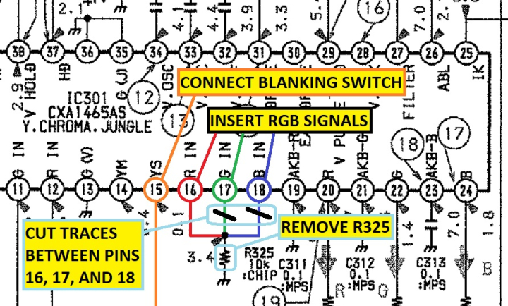
The red, green, and blue inputs are on pins 16, 17, and 18. They are tied together on the PCB and connected to ground via a 10k ohm resistor.
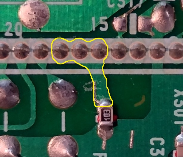
To insert our RGB signals, we need to carefully separate the 3 pins by cutting the traces between them on the PCB. Then, the 10k ohm resistor (R325) must be removed.
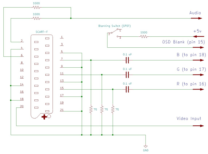
Each RGB line must have a 75 ohm terminating resistor to ground and a 0.1uF inline capacitor before connecting to the chassis. Blanking should be connected to a +5v supply via a 1000 ohm resistor and a SPDT switch. Sync (ideally in the form of composite video or luma) should be connected to the rear video input. Left and right audio are mixed using 1000 ohm resistors and routed to the rear audio jack.
If using a SCART connector, wire it up as follows:
Along with the 3 RGB input pins, attachment points for blanking, +5v, and ground can be found near the jungle chip.
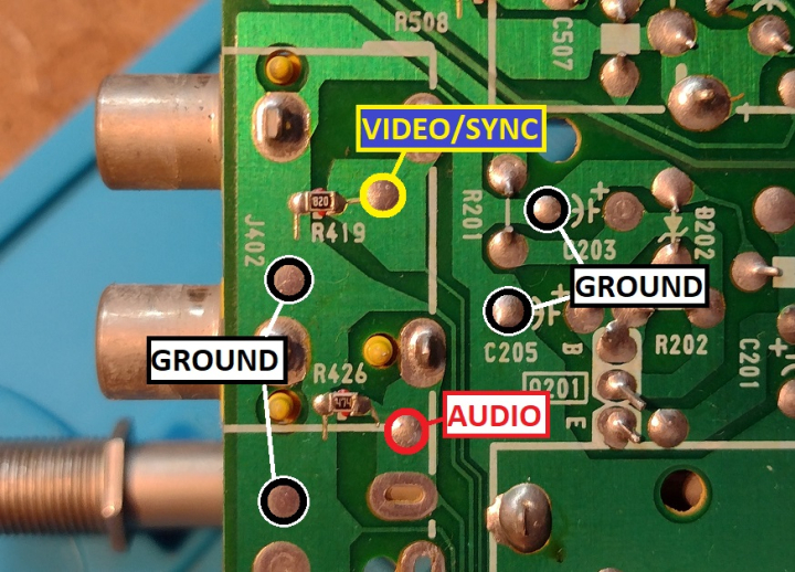
Audio and sync signals can be connected to the bottom of the AV input jacks.
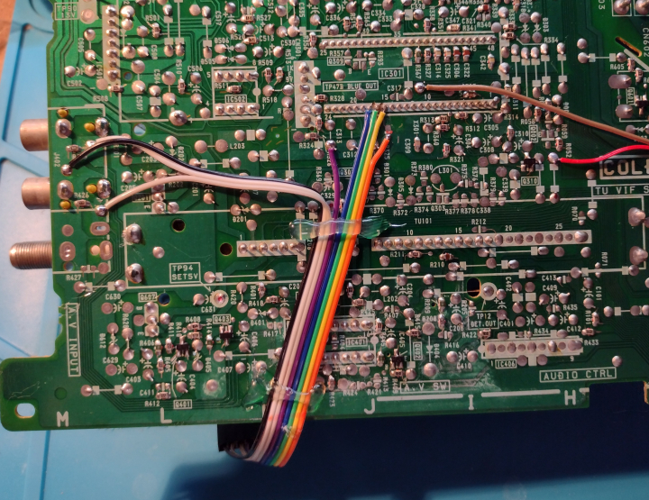
I used 26 gauge ribbon cable for wiring, secured with a bead of hot glue and routed off the left hand side of the PCB. Note that there is only a small gap between the front and back halves of the case, so precise placement is important. Alternatively, if separate wires are used, there are several small holes near the tuner through which they can be routed to the top of the PCB.
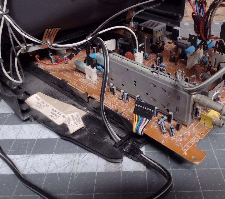
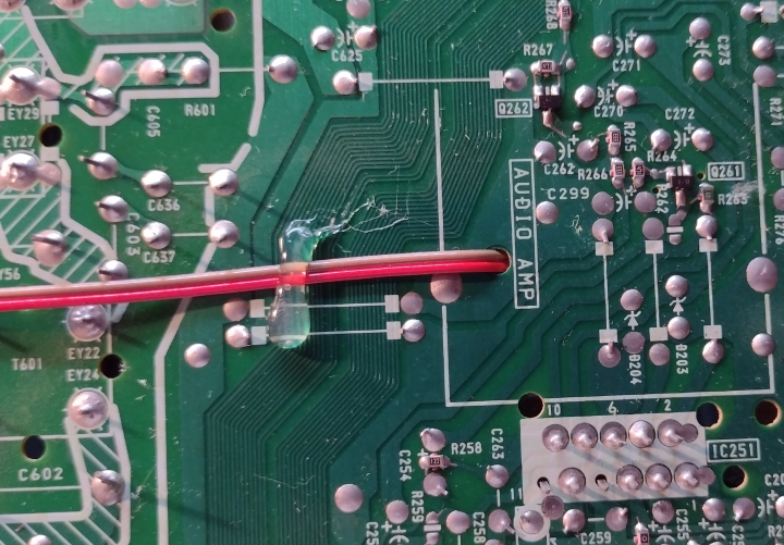
Wires for the blanking switch were routed towards the front of the chassis, through a hole in the audio amp section.
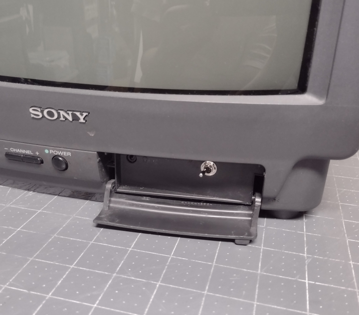
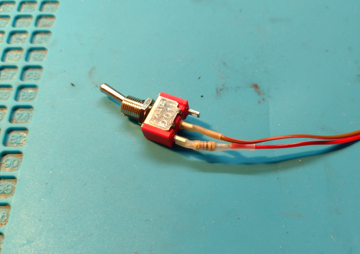
The 1000 ohm resistor is attached to one leg of the blanking switch, which is mounted on the front panel and connected to the chassis via a quick connect.
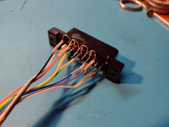
The SCART connector is wired up with all ground pins connected together, 75 ohm termination resistors installed, and 0.1 uF capacitors inline with the RGB leads. For more information, visit the SCART installation guide.
I chose to mount the SCART connector horizontally, above the A/V ports. However, installing it in this location can be difficult due to the thickness of the case and ventilation slits in this location. Mounting it vertically to the left of the rear label would be simpler and more accessible.
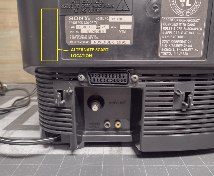
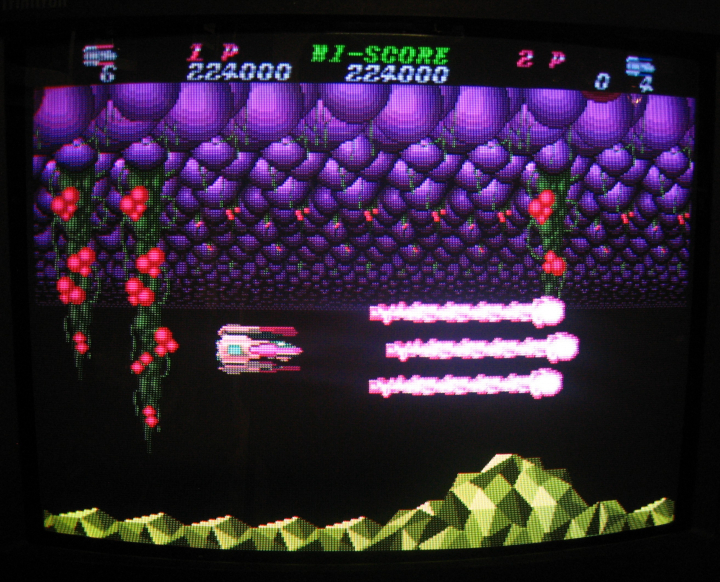
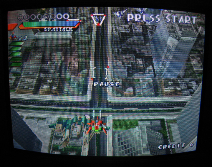
Now that the mod is done, the TV will display a clean RGB image when the blanking switch is enabled and the TV is set to the A/V input. The picture may be shifted horizontally somewhat. To compensate for this, refer to the service manual and adjust HPOS so that the image is centered.
Gallery

| Specifications | |
|---|---|
| Brand: | Sony |
| Manufacturer: | Sony |
| Model: | KV-13M10 |
| Series: | KV |
| Viewable Size: | 13" |
| Inputs: | Composite, RF |
| Native Resolutions: | 240p, 480i |
| Horizontal Scan Range: | 15 kHz |
| Vertical Scan Range: | 60 Hz, 50 Hz |
| Formats: | NTSC |
| Aspect: | 4:3 |
| Adjustments: | OSD Customer Controls, OSD Service Menu |
| Horz. Output Transistor: | 2SD1877S |
| Vertical Output IC: | LA7830 |
| Jungle IC: | CXA1465AS, CXA1865S |
| Comb Filtering: | None |
| Flyback: | 1-453-142-11, 1-439-421-11, NX-1702A5 |
| Tube: | Sony Trinitron , A34JBU10X , A34JBU70X |
| Heater Voltage: | 6.3v |
| Deflection: | 90° |
| Mask: |
Aperture Grille

|
| Tint: | Dark |
| Removable Glare Film: | No |
| Yoke: | 8-451-418-11, Y14NDA2 |
| Yoke Horz. Inductance: | 2.794 mH (@ 10 kHz) |
| Yoke Vert. Inductance: | 20.39 mH (@ 100 Hz) |
| Yoke Horz. Resistance: | 5.049 ohm |
| Yoke Vert. Resistance: | 10.64 ohm |
| Speakers: | Mono |
| Remote: | RM-Y116 |
| Chassis: | BA-2 |
| Weight: | 22 lbs (10 kg) |
| Application: | Consumer |
| Launched: | 1995 |
| Country of Manufacture: | Mexico |
| Mods: | RGB via Direct, S-Video |
| Degaussing: | Automatic on Power-on |
 This work is licensed under a