Summary
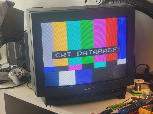
An interesting departure from typical Sony chassis design. Has a quirky "Service Mode" button hole on the back that I've never seen on any other Sony TV, as well as PIP support (weird for a 20" TV) that enables an analog RGB Mod. Also has pincushion, h-width, h-center, v-height, and v-center adjustment in the service menu!
Literature
Notes
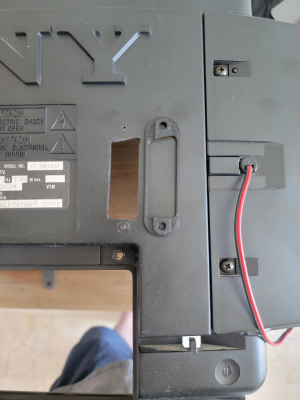
Service menu is accessed by pressing a pen into the unmarked hole in the back near the S-Video input - with the button pressed down, press Power on the remote (or the front of the TV). Now you're in service mode.
Support for 50Hz video can be enabled by adjusting "VSMO" in the service menu.
From there, you can navigate the service menu like many other Sonys, using 1/4 for scrolling the options and 3/6 for scrolling the values. To save your changes, press MUTING then ENTER, then unplug the TV from the wall.
If you see vertical bars/shadows on the left side of the screen, replace C704, the 4.7uF 250V capacitor on the neckboard.
In the video settings menu, there's an option to toggle a Notch filter. This may be beneficial for some video game consoles using Composite.
RGB Mod
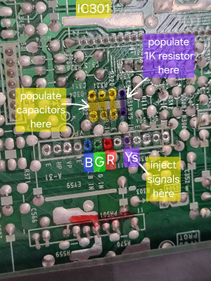
The RGB mod on this is relatively simple. First you need to find the unpopulated "PIP header" on the main board. It is located in the rear between the flyback and input board area. It is labeled "A-31" and the silkscreen shows labels for R, G, B, E (gnd) and YS (blanking).
Next to the PIP header is a group of four unpopulated resistor spots (R322, 321, 320, and 319). Populate them with the following:
- R322: 0.1uF film capacitor
- R321: 0.1uF film capacitor
- R320: 0.1uF film capacitor
- R319: 1K resistor
See gallery below for a graphic showing this.
If want to keep the composite/s-video inputs working, you need to add a switch on the blanking voltage (or rely on your SCART device to provide blanking voltage). You can pull 5V from the tuner (TP96A labeled 5V), run a wire from that to a single pole switch, and run the other end of the switch to the "YS" pin of the PIP header. Otherwise, if you don't care and just want RGB to work, you can run a wire straight from 5V to the YS pad on the PIP header.
For sync, you need to connect it to one of the video inputs. I suggest using one of the composite inputs, because the S-Video connector has a pin detection that needs to be bypassed before you can use it for sync, and bypassing that requires more switch wiring etc. Personally I just connected my sync wire to the pad for composite on Video 2. In order to access any of these pads, you need to remove the metal shield from the back of the input board. It is held down with 4 screws, and they can be removed without any additional disassembly as long as you have a long enough screwdriver to maneuver the situation.
For ground, you must run a wire from ground on your input connector(s) to either a ground point on the input board, or the "E" pad on the PIP connector from earlier. Whatever you find to be easier will work fine.
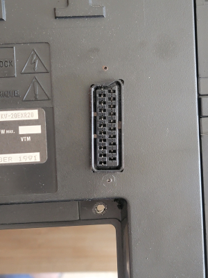
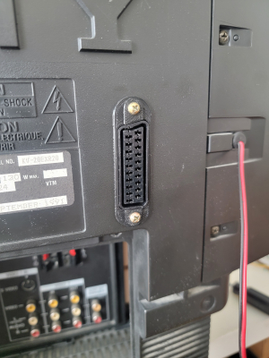
Next you'll need to take your RGB signals and wire them to the R, G, and B pads of the PIP header too. Don't forget to add 75ohm termination resistors - they should be either at or before the PIP header connection, and should be tied between each signal and ground. Here is a great guide on how to do this with a SCART connector. Optionally you can also use BNC connectors but you will have a hard time fitting them all on the back of the input board. I put them in a 2x2 formation (see pictures - if you go with BNC remember you need to connect ground for at least one of the connectors!).
As for choosing a mounting location for your input connections, I always recommend trying to keep your inputs on the input board area so that the TV can still be disassembled properly. If you mount your input connectors on the removable shell part of the TV, it will get pulled away from the wires when you try to take the back cover off of the TV. This increases both your wire length (introducing noise) and the chances of damaging your mod during basic disassembly.
Gallery



 This work is licensed under a