Summary
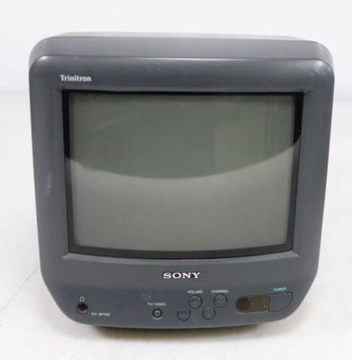
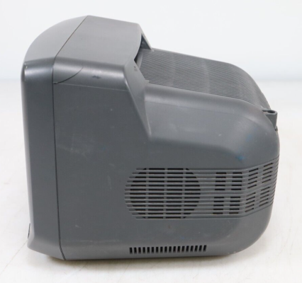
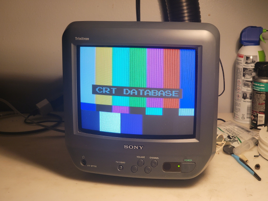
The dark grey AC/DC-powered KV-9PT60 (and its AC-powered white-plastic sibling the 9PT50) are both 9" viewable CRTs often referred to as "kitchen TVs" due to their compact size and ability to be mounted under cabinets if you have the optional hardware. They came in two colors: white (PT50) and dark grey (PT60). The white ones often experience plastic yellowing, and the grey ones seem prone to brittle plastic disease.
The other similar models are the 9PT20 and 9PT40, and although they look nearly identical to the 50/60 there are some critical differences internally that make the 50/60 model more desirable. Their CXA1464AS jungle chip has unused analog RGB (and S-Video) inputs that make this a relatively easy modding project, at least for wiring. The 20/40 models use an LA7672 jungle chip which CANNOT be RGB modded. Additionally the 50/60 model has a digital OSD and service menu for color and geometry adjustment, while the 20/40 model uses analog potentiometers.
Inside you will find a separate PCB for the power supply, due to the DC input this model supports. The AC-only 9PT50 model is a single board design inside.
Literature
Notes
Like most other 9-10" consumer-grade CRTs, this has imperfect horizontal linearity due to chassis design. There is no horizontal linearity correction coil to ensure the horizontal timing is consistent through the whole scanline. The circuit is omitted for cost cutting. This means if you view a grid pattern you will see the right side of the screen is squished horizontally. Generally you won't notice this during gameplay or viewing. See grid picture in the gallery below.
Both the picture settings menu and the service menu require a remote to access. Pretty much any Sony remote will work.
Picture Menu: Press MENU on the remote, then select SET-UP.
Service Menu: Power the TV off, then press DISPLAY + 5 + VOL UP + POWER in relatively quick succession to boot the TV into service mode.
You can scroll through the settings with 1 and 4 on your remote, and adjust the setting values with 3 and 6.
Once you're done, you can save your changes by pressing MUTE then ENTER.
Note that HSIZE and pincushion controls will not work. This TV does not have the necessary components to utilize those settings. There is a horizontal width coil inside the TV you can adjust if you need to.
This CRT does not have horizontal static convergence (H-STAT) adjustment. All convergence adjustment must be done traditionally with the rings and convergence strips. Corner convergence is typically not great on these.
RGB Mod
Written by Andy King
The RGB mod on this chassis is very straightforward but tedious in the amount of preparation it requires and the skill necessary for clean execution - the devil is in the details. There is no muxing required, you just send properly attenuated RGB signals to the correct pins on the jungle and supply a blanking voltage. I don't recommend attempting this as your first RGB mod. Make sure you read the whole guide before making modifications to the TV.
Main challenges:
- The RGB input pins on the IC301 CXA1464AS are grounded since they are unused. You will need to isolate them from ground. There are 3 ways to do this, which I will go over below.
- There is not enough room on the back of the input board plastic for a proper SCART connector or BNC array of inputs. You have a few different choices here which I will cover.
Choosing an RGB input method
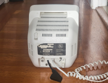
Since there is no room to mount a full size RGB input connector on the back of the TV without seriously mangling the case, my recommendation is to make a pigtail / dongle on the back for a SCART connector or BNC connectors, depending on your preference. Keep in mind SCART has the advantage of properly carrying stereo audio (which you can mix down to mono with just two resistors) and a blanking signal, as well as workspace inside the connector head to fit coupling capacitors, terminating resistors, audio mux resistors, etc.
There are two different options I recommend:
- Drill a hole and put a mini-DIN8 connector on the back. This allows you to disconnect your RGB pigtail / dongle when you aren't using it. If you follow the XRGB pinout you'll be able to use an off-the-shelf XRGB-mini to SCART or MD to SCART cable as a base for your dongle.
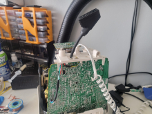
- Drill a hole and put a SCART dongle straight through the back for a permanent installation. You will need to put some kind of strain relief clamp inside to prevent the dongle from being pulled out or pushed in.
Instead of min-DIN8 you could also fit a VGA or DB9 connector but it will require a lot more cutting and mangling.
In any case, you will need to make sure the wire and connector you choose supports at least 6 signals... 7 if you want switchless blanking (see the "Hooking up Blanking" section below for more info on this). For wire I suggest either an old VGA cable, printer cable, etc. Something with a lot of wires. If you feel fancy you can order some Fortaflex cable from Retro-Access, which is what I personally had on-hand and used for this project. Keep your dongle cable short if its unshielded, longer unshielded wires increase the risk of signal noise.
Wiring your SCART input
Hopefully you picked SCART as the input connector for your mod - if you picked BNC you'll have to implement all of these components on the PCB end of the wires instead :)
Your RGB signals need to be coupled and terminated. I suggest doing this inside the SCART head by following this guide. At the step where you connect your R, G, and B wires to their pins on the SCART head, insert a 0.1uF film capacitor in series for each one to couple the signal. IMO doing it here is easier than doing it on the PCB side near IC301, but it's up to you which side you choose.
Sync, blanking, and audio will be discussed in separate steps below.
Hooking up RGB to IC301 (CXA1464AS)
On IC301, pin 16 is Red in, 17 is Green in, and 18 is Blue in.
You have 3 options, which I will order here from most-preferred to least. You can pick what seems easiest for your skill level and available tools.
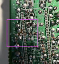
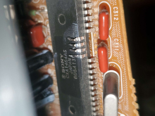
- Completely extract the solder from all 3 holes using one of the following: good wick (cheapest and easiest), a good solder sucker, or a solder pump such as the Hakko FR301. Then solder your wires directly to the desoldered leg ends, using heatshrink to prevent them from touching each other. The PCB holes are not conductive so you don't need to worry about the IC301 legs intermittently shorting to ground once you desolder them.
- Cut the traces between the pin pads + ground using a grinding pen or a very sharp craft knife. Be careful not to cut more than you have to, and verify your work with a multimeter in continuity mode.
- Cut the 3 legs of IC301 right above the top PCB surface and bend them outwards to form a platform for soldering to them.
Run your terminated, coupled RGB signals from your dongle to these now-isolated input pins on IC301.
Example photos in order of method 1, 2, and 3:
Hooking up Blanking to IC301 (CXA1464AS)
You can solder your blanking wire to IC301 pin 15. On the other end of your blanking wire you will need to add a generic 0.7v diode such as a 1N4148 and a 1Kohm resistor in series. The order does not matter, but the cathode of the diode (stripe side) must be connected towards IC301, not your input source. The resistor is for load and current limiting, and the diode is to prevent backfeeding of blanking voltage from the TV to your input source.
You have two choices for blanking:
- You can supply blanking from a SCART connection (pin 16) to make the mod a switchless install. This is probably a great option for 95% of people. The only time this is not a great option is if you want to connect devices that do not supply a blanking voltage, or want to use an RGB connector that does not supply blanking voltage (such as BNC).
- You can install toggle switch for blanking. One side should be wired to a 5v source in the TV (such as Pin 3 of the tuner TU101, or the + side of a 5v rail filter cap like C631, or any other place where "SET 5V" runs in the TV - don't use STBY 5V), and the common pin goes to the blanking wire described above. You could even get a SPDT switch and use the other pole for SCART blanking. This lets you have the best of both worlds.
5V source (from either SCART or TV) -> 1k resistor -> diode -> IC301 pin 15
Hooking up Sync, Audio, and Ground
Your sync wire needs to be soldered to the input pin for composite video.
Similarly your audio pin needs to go to the input pin for composite audio. It is a good idea to try and implement stereo to mono mixdown on your audio input so that you can hear both channels of game audio. Many games only output important sounds on a single channel so if you don't use stereo audio as a source you will miss out on a lot.
It is very simple to mix down stereo to mono - you simply pick two resistors that are identical in value (such as 1K) and put them in series on the audio inputs. One for the left channel and one for the right. You can tie the two output legs together to form the single mono channel. This mono output can be wired directly to the composite audio input pin. I suggest doing this resistor work inside your SCART head.
Gallery




 This work is licensed under a