Summary
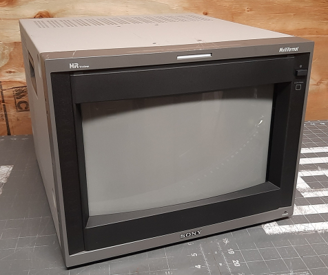
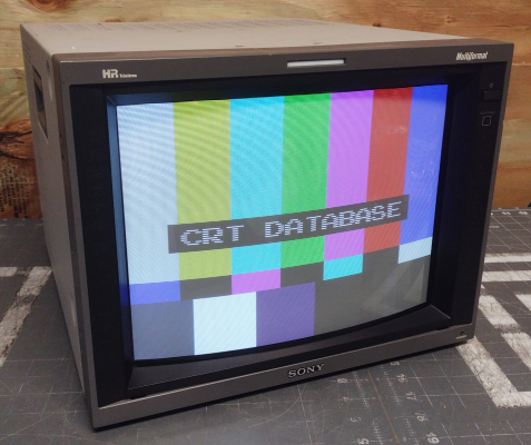
Multi-sync broadcasting 4:3 aspect CRT from Sony that supports signals from 240p through 720p and 1080i.
Manuals
Media & Promo Materials
Replacement Part Patterns
Notes
Earlier serial numbers (the production range cutoff is somewhere around 2003) of the 14L5/20L5 D2 boards have a horizontal linearity defect which only appears in 15Khz signals - it resembles the same linearity issues you'd see on something like a KV-9PT50/60 (or any other CRT which lacks a horizontal linearity coil) where the left side of the picture is horizontally-narrow and the right side is wide. You can see it most prominently by displaying a grid pattern or using the Scroll Tests in the 240p Test Suite. There is no known fix at this time other than swapping a newer-serial-number D2 board into the chassis. There is a commonly referenced service bulletin that appears to address this issue, but the listed fix does not work - in fact it makes the problem worse.
The 14L5 uses the same tube, yoke and flyback as the BVM-D14HU. The same flyback is also used in the PVM-20L5, despite the difference in size between these two monitors.
Common Problems
Similarly, do not try to take live multimeter measurements of your L5 while it is powered! Leave it to the professionals, serious damage can occur.
Acquired G Board Syndrome (AGBS)
There is an increasing number of G-board related failures in these L5 units. The cause is still unknown but there are community members researching the problem. It seems to happen out of nowhere. One day your L5 will shut itself down and restart. Initially this could appear random but gradually, it will turn into a reset death loop.A good test to see whether your monitor is beginning to develop AGBS is to display a full-white raster. If after a while the monitor has not reset you are likely OK. There is no known fix at this time other than swapping in a working G board. Recapping does not fix it.
Cold spraying on or around IC602 stops the AGBS death loop. (albeit temporarily, until components warm up again). An attempt to replace IC602 wasn't succesful in fixing the issue. Earlier G board (green PCB) seem less prone to AGBS than later PCB (blue PCB's). Evidence for this assertion is limited at this time.
- How do I remove the neckboard? - The neckboard is held on by both a ring clamp AND a plastic holder with 3 arms that stick through the PCB. First, you must loosen the screw on the ring clamp. You don't need to remove the screw, just loosen it until the ring can be freely spun around the CRT neck. Next, get a good solid grip on the neckboard PCB and rock it back and forth, as well as side to side, slowly working the plastic loose from the cloth tape on the CRT neck. Once the plastic is all free, you can wiggle the neckboard off the CRT neck entirely. I don't recommend removing the plastic holder at all unless absolutely necessary. I just leave it clipped into the PCB because its usually ready to break under any amount of tension.
- Screen goes bright white and then shuts down - likely R705 has blown on the neckboard. This little 39ohm nonflammable/fusible resistor functions as overcurrent protection for the 200v voltage rail coming into the neckboard via CN701 pin 3. If this resistor is blown, likely you have a short circuit on the load side of the resistor. Don't replace this resistor until after you check for and clear any short circuits that are occurring on the load side. If you don't clear the shorts, all replacement resistors will subsequently blow up. Take care to replace this resistor with another nonflammable resistor, otherwise you are introducing a fire risk. The 160v rail will continue to supply high current while the resistor burns. To check for a short circuit with a blown R705, put one multimeter probe on GND (you can use the one on CN701) and the other probe on the load side of R705 (the left pad if looking from the back of the PCB). If you see a resistance of less than 100ohms or so, you have a short circuit on the neckboard. The most common reason for a short on the neckboard is one or more of the TDA6120Q's (IC701/702/703) going bad. These are high power amplifier ICs that control color output directly to the tube. You can narrow down which one(s) are shorted by desoldering pin 10 of each, one at a time, checking resistance to ground after desoldering each to narrow down when the short disappears. Savon-Pat's capacitor kit on eBay includes one replacement TDA6120Q and one nonflammable 39ohm resistor to address this problem.
- Monitor makes clicking noises repeatedly instead of turning on - if you have an active input signal connected to the monitor, disconnect it (or turn the source device off) and then try booting the monitor again without that active signal. Sometimes the monitor gets stuck trying to detect the signal during the boot process.
- Monitor works fine for a few minutes and then shuts down - This is likely a failure on the G board power section - research is still being conducted on what the cause and solution to this problem is. It seems to plague many L5 series PVMs.
- Blurry Corners - There are two different areas to adjust focus on an L5 - via the service menu FOCUS screen and via the flyback. Generally the service menu focus options should not be changed - rather you should adjust the flyback. There are two knobs on the flyback - the top one adjusts H focus and the bottom one adjusts V focus. Likely you will be able to get your corners VERY sharp by just a slight adjustment of the top H Focus knob.
14L5 vs. 20L5 G board differences
Due to scarcity of parts you might need to convert a 14" G-board into a 20" or vice versa.
Sony PVM 14L5 to 20L5 G board differences.

20L5 Added components:
R567     1-216-097-00 RESISTOR CHIP 100K 1/10W(2012)
CN507    1-564-507-11 PLUG,CONNECTOR (4P)

No components removed.

Modified components:
Silkscreen part number:
  14L5: 8-330-030-08
  20L5: 8-330-030-43
R535:
  14L5: R535     1-249-401-11 RES,CARBON 47 1/4W (SMALL)
  20L5: R535     1-249-397-11 RES,CARBON 22 1/4W (SMALL)
R565:
  14L5: R565     1-216-295-91 CONDUCTOR, CHIP (2012)
  20L5: R565     1-216-645-11 RESISTOR,CHIP 560 1/10W(2012)
R514:
  14L5: R514     1-216-675-11 RESISTOR,CHIP 10K 1/10W(2012)
  20L5: R514     1-216-667-11 RESISTOR,CHIP 4.7K 1/10W(2012)
R536:
  14L5: R536     1-249-397-11 RES,CARBON 22 1/4W (SMALL)
  20L5: R536     1-249-393-11 RES,CARBON 10 1/4W
IC503:
  14L5: IC503    8-759-140-85 IC UPC1093J
  20L5: IC503    8-759-198-31 IC UPC1093J-1-T
R534:
  14L5: R534     1-249-397-11 RES,CARBON 22 1/4W (SMALL)
  20L5: R534     1-249-393-11 RES,CARBON 10 1/4W
R511:
  14L5: R511     1-216-684-91 RESISTOR,CHIP 24K 1/10W
  20L5: R511     1-216-678-11 RESISTOR,CHIP 13K 1/10W(2012)
R538:
  14L5: R538     1-216-065-91 RESISTOR,CHIP 4.7K 1/10W(2012)
  20L5: R538     1-216-073-00 RESISTOR,CHIP 10K 1/10W(2012)
R650:
  14L5: R650     1-216-387-11 RESISTOR,METAL FILM 0.68/3W
  20L5: R650     1-216-386-11 RESISTOR,METAL FILM 0.56/3W
Gallery

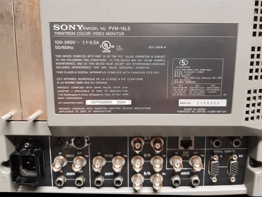
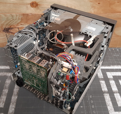


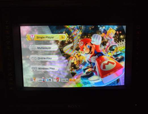
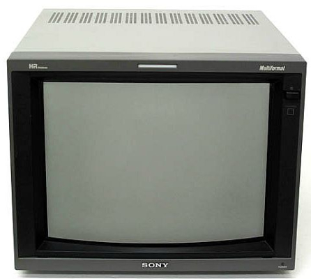


 This work is licensed under a