Summary
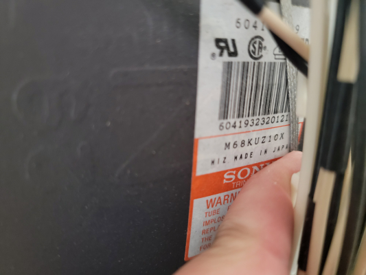
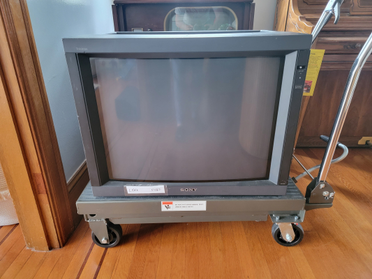
Modern redesigned version of the PVM 2530 with a larger tube and all-digital controls. The tube is quoted by Sony as 29" but only 27" is viewable. Specifically the tube model number has the M68 prefix which indicates a total diagonal viewable size of 68cm (26 3/4").
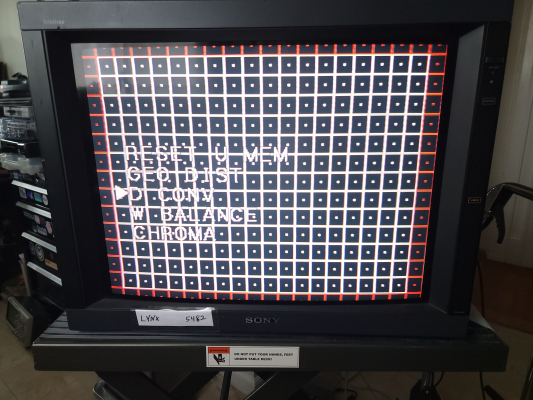
The most noteworthy feature of this model is the digital convergence adjustment options, which is part of the onscreen display for configuration. There are no internal adjustment pots for geometry calibration - everything can be done digitally via the user menu and service menu. This makes it the most easily configurable PVM ever made. The digital convergence adjustment is almost on par with those available in Sony BVMs and Computer Monitors - it even has Tilt and digital H-STAT adjustment (labeled DC Offset in the service menu).
Sony recommends their accessory model TU-1040E TV tuner for television broadcast viewing, and speakers model SS-X7A. The APM-X5A speakers are functionally and physically exactly the same speakers but with square APM cones instead of traditional round ones. You can find more in-depth information about the speakers from Sony on this guide.
Literature
Notes
The remote you use with this monitor must have a "Display" button, "Menu" button, "Mute" / "Muting" button, and "Enter" button in order to fully control the service menu.
You can access the service menu by first turning on the TV via power switch, then putting the monitor in standby using the power button on a Sony remote. Next you will press DISPLAY -> 5 -> VOL UP -> POWER. The monitor should boot into the service menu. Press 1 or 4 to scroll up or down, 3 or 6 to change setting values up or down, 2 to go back a menu (first to a WRITE confirmation screen, then again to go back to previous menu), and Enter (or 12 if using the RM-854) to select a menu option.
To save your settings after making changes, first press 2 to bring up a menu that says "WRITE MEMORY" on it. Next, press "MUTE" (some remotes call it "MUTING") to toggle the "WT" status next to where it says "WRITE MEMORY". Finally to save to memory, press "ENTER" (or "12" if you are using a Japanese remote). The "WRITE MEMORY" text should then turn blue to indicate the data is being saved. If you don't see the text turn blue your remote is not sending the correct signals and you should try other buttons or get a different remote. The very common RM-Y116 is cheap to buy and fully supports all of these required functions. The "official" remote for this monitor is the RM-854. Another popular choice is the RM-Y181.
The digital convergence menu is very powerful - most convergence issues can be resolved without using strips. Refer to the service manual for diagrams on what each option does. DC Offset is not described in the manual but it is just a digital adjustment of the H-STAT knob. It will adjust horizontal convergence for the entire screen.
Repair Notes
Vertical Bowing / Pinching distortion that isn't due to yoke sag
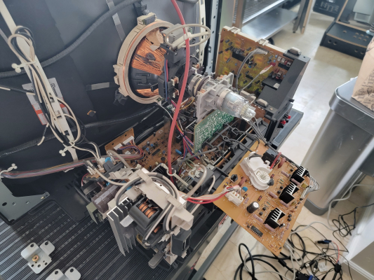
A lot of the geometry on this set is controlled digitally so if any components related to it fail then you start to see geometry issues. There is a common failure on the VC board where the solder joints for some of the transistors start to fail due to heat. The board is mounted vertically and as the transistors heat up they start to sag under their own weight and the solder joints become compromised over time. Try reflowing their solder, starting with Q1807, and see if the issue is resolved.
Power Supply
The power supply in these has a standby circuit that runs 24/7 off a secondary 30v transformer in the power supply. This 30v power drives a 12v and 5v STBY rail, and the STBY rail is used to put the main computer in a low power state waiting to get a wake-up signal from either the power switch or a remote command. The wake-up command is called RES (reset) and it is held high (5v) if the monitor is supposed to be turned off. If there is any problem that the monitor detects, it will keep the RES signal high regardless of power switch state. Otherwise, the power switch will toggle the microcontroller on the H3 board to latch RES low and allow the main computer to wake up, which will start up the rest of the monitor.
If you suspect a problem with the STBY startup circuits, you can actually bypass it temporarily by grounding the anode of D641 (on the G board) - I do this using an alligator clip, clip one to the anode and one side to ground. This will allow the main AC relay to latch, which will supply power to the primary side of the power supply where B+ and other rails are generated. As long as there are no problems with the rest of the circuitry in the TV, it should start up and energize the CRT. You should hear high voltage and 15kHz oscillation. You won't be able to see anything on the screen since the computers are all still in STBY mode... But at least you'll know the actual horizontal and high voltage side of the CRT works fine and your problem is localized to the RES/STBY circuits.
I worked on one 2950Q where it wouldn't power on at all, even though the standby circuit was active and seeming to work fine. The problem turned out to be IC871 on the H3 board. If that IC is bad it won't allow the RES signal to latch low, which means the main computer will stay asleep and ignore you pressing the power switch. You can test for this very easily! Simply unplug the H3 board from the A board (leaving everything else still plugged into the H3 board itself) and the TV should turn itself on when plugged into AC. If this fixes your problem you have either a bad IC on the H3 board or there is a problem with your H2 board (the front panel control board). Keep in mind with the H3 board unplugged the front panel won't work for controlling the TV. You can find a detailed repair log of how I fixed that on my Patreon.
Removing the Front Panel Control Board (H2 Board)
I suggest removing the metal support bracket before trying to remove the front panel - it has passthrough holes on it for undoing the screws but the cllips are very hard to get when you can't see them... so remove the bracket first before continuing. The screws in this board are not meant to be fully removed - simply unscrew the 4 screws on the back until they are just turning in-place, then unclip the panel. There is one clip on the top and one on the bottom, use a flashlight to see what you're doing. Don't break the clips. Once you undo the clips you can push the panel out from inside/behind.
Once you remove the front panel there are several clips to hold the PCB in place. Once you remove the PCB there are buttons inside that will fall all over the floor - so I suggest laying it face down first to avoid that mess. With it laying face down you can undo each of the clips holding the PCB in place.
Mysterious Corner Brackets Fall Out During Disassembly
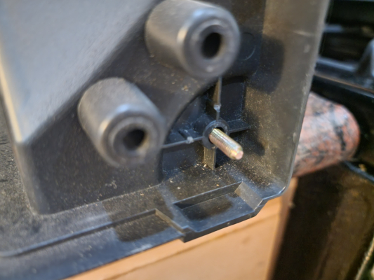
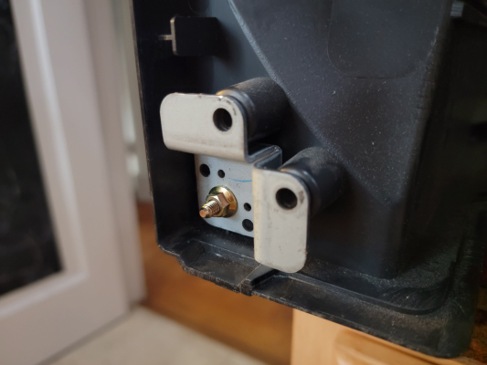
When taking apart your 2950Q for the first time you may notice one (or both) corner brackets, along with a hex nut, falling out from near the bottom corner of the PVM front-half. These pieces, for whatever reason, have a tendency to come unscrewed over time and are important to install properly for full integrity of the cube chassis design. Sometimes the screws disappear inside the rear cube assembly - you can make them reappear by tilting it downward and shaking it a little until they slide back out. Once you see them, slide the bracket back on and reinstall the nut until the bracket is tight (see bottom of page for images)
Gallery



 This work is licensed under a