Summary
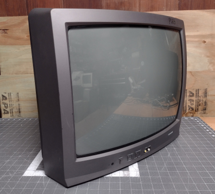
A basic, low end TV manufactured by Orion and sold by Toshiba. It has composite input and a single 1 amp speaker that's mounted on the bottom of the TV. It is unique, however, in that it has a genuine 20" tube and is straightforward to modify for RGB. This makes it a potential replacement for 19" arcade monitors.
Literature
Notes
19" TVs are relatively rare in the US market; most TVs in this size range have 21" tubes with a 20" viewable area. Because of this, the tube can be used as a replacement for Wells Gardner K7000 series arcade monitors (provided that the chassis has a 10-pin neck board). The chassis is compact and, with an RGB mod, the whole TV can be used as a sustitute if a working arcade chassis is not available.
This particular model is the only Orion-produced 19" Toshiba that can be RGB modded. Later versions of this TV use a 1-chip chassis that does not have RGB inputs.
The 13A21 uses the same chassis design as this TV and can be modified in the same way.
Like other Orion TVs, this model lacks an input select button on the front panel, and cannot change video sources without the remote control.
RGB Mod
Written by Matt Ross (6tanks)
Adding RGB to this TV can be done via the OSD mux method. As can be seen in the service manual, each OSD signal passes through a voltage divider and a 0.1uF coupling capacitor on its way to the jungle chip.
![]()
To insert our RGB signals, we need to remove the 3 resistors to ground (R102, R103, and R104), and connect the RGB signals before they pass through the 0.1uF capacitors. If using a SCART connector, wire it up as follows:
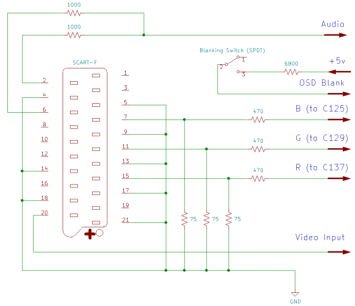
Each RGB line must have a 75 ohm terminating resistor to ground and, to maintain OSD function, a 470 ohm inline resistor before connecting to the chassis. Blanking should be connected to a +5v supply via a 6800 ohm resistor. Sync (ideally in the form of composite video or luma) is connected to the front video jack. Left and right audio are mixed using 1000 ohm resistors and routed to the front audio jack.
The 3 resistors that need to be removed are all located near the top of the microcontroller:
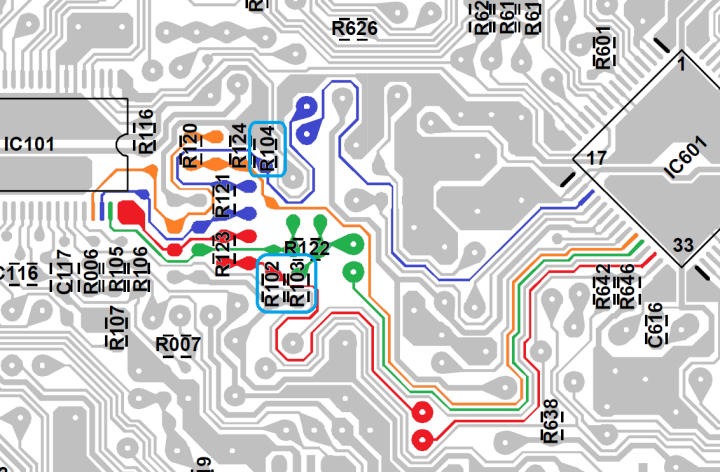
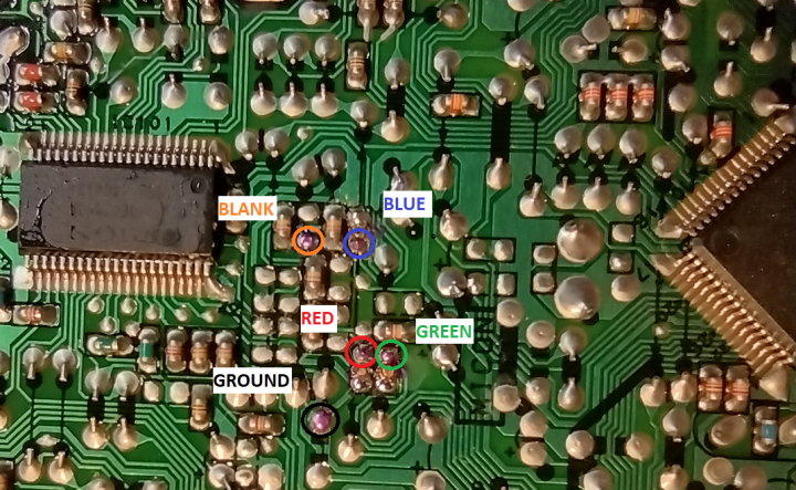
After the resistors are gone, this area provides good attachment points for the RGB signals, blanking, and ground:
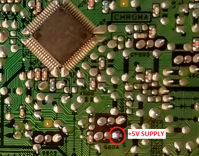
The +5v supply for the blanking switch can be taken from one of the voltage regulators near the jungle chip:
There are some useful solder points for Sync and Audio near the front A/V jacks:
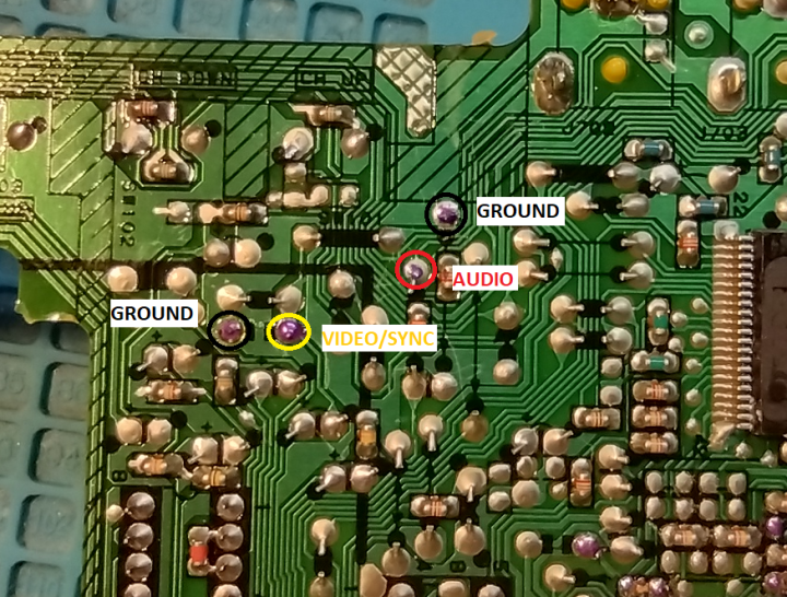
I used 26 gauge ribbon cable for the RGB and blanking signals, and coax for sync and audio. With everything soldered in place, the wiring can be run through the large hole to the top of the PCB and secured to the metal tiedown for the speaker wires. It's a good idea to use a quick connect so that the back case can be easily removed:
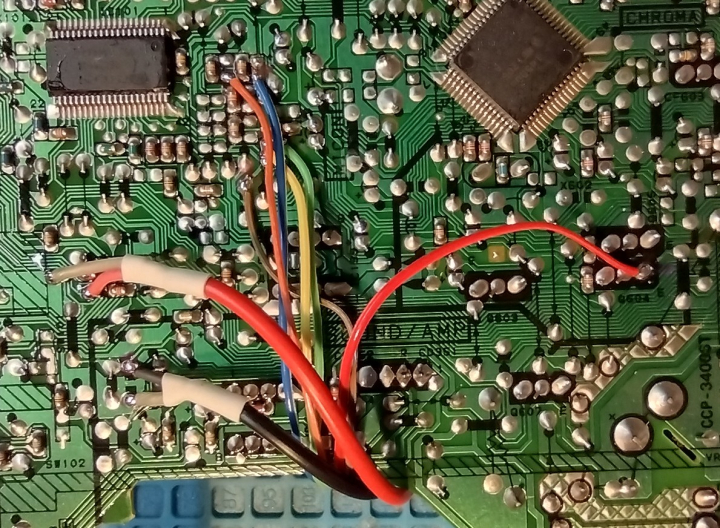
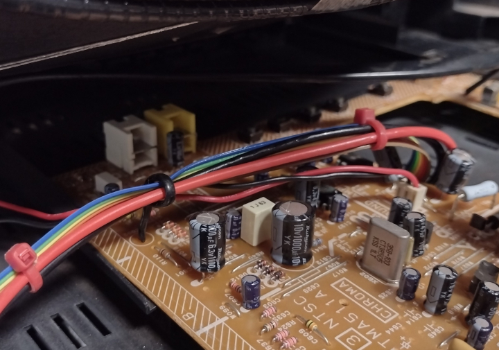
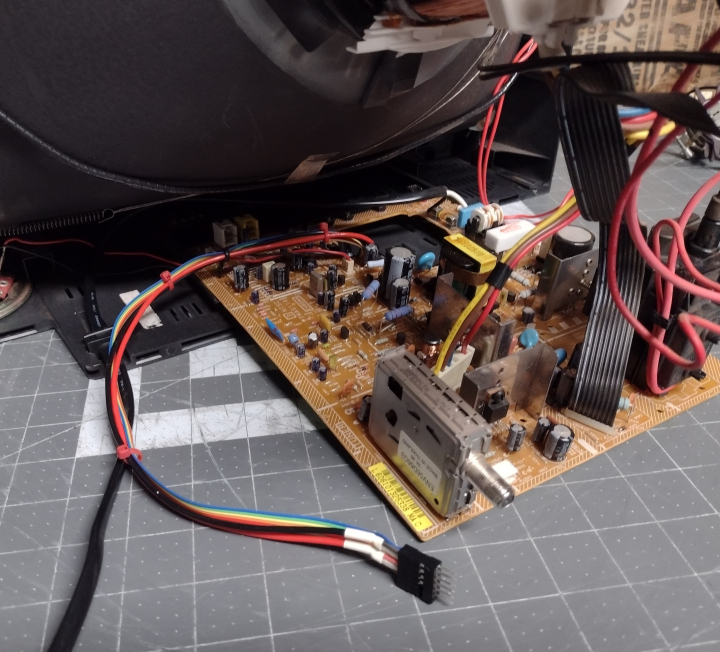
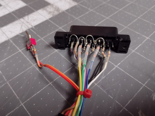
The SCART connector is wired up with all ground pins connected together, 75 ohm terminating resistors installed, and mux resistors in line with the RGB leads. For more information, visit the SCART installation guide.
The 6800 ohm resistor is attached to one pole of the blanking switch.
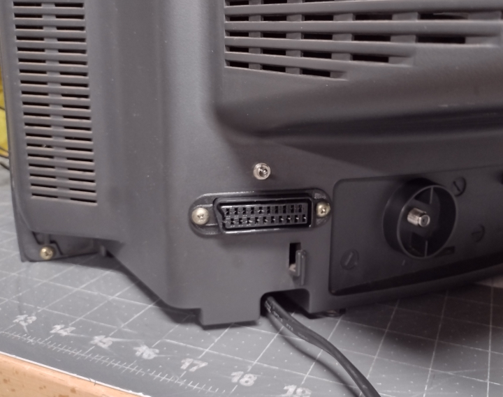
The SCART socket fits nicely to the left of the RF tuner. This gives it plenty of space and keeps the wiring away from the power supply, which can cause interference.
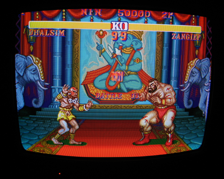
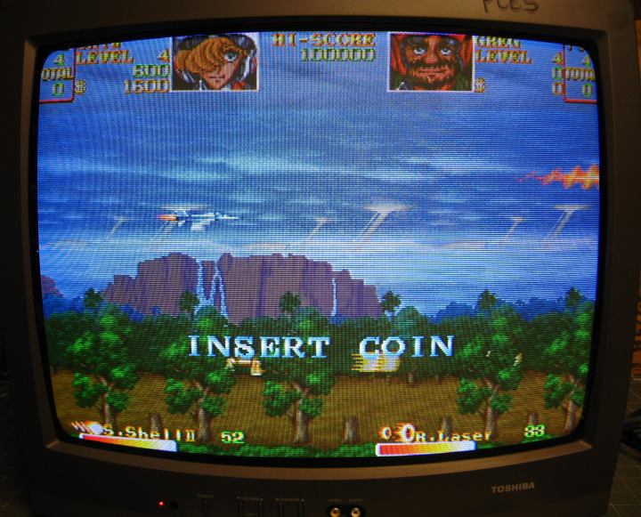
Now that the mod is done, the TV will display a nice clean RGB image when the blanking switch is enabled and the TV is set to A/V input. The picture will be shifted horizontally somewhat. To compensate for this, refer to the service manual and adjust H Phase so that the image is centered.
Gallery



 This work is licensed under a