Summary
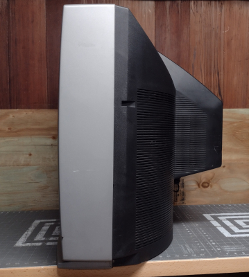
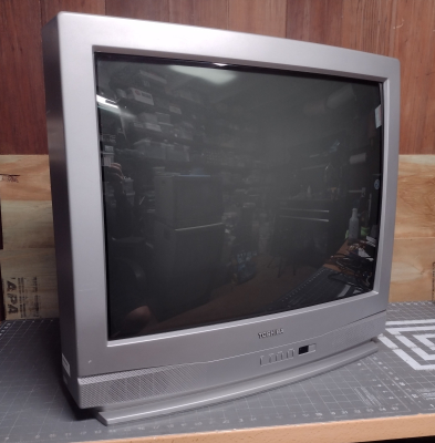
Produced in 2003, this was among the last CRT Televisions produced by Toshiba. At this time, their 27" and smaller TVs were rebranded Orion sets, but the 32" and 36" models were still manufactured by Toshiba themselves. Beginning in 2004, they stopped manufacturing CRTs altogether and outsourced all their production to Orion. Genuine Toshiba televisions are noticeably higher quality and have a cleaner picture than their Orion-made counterparts.
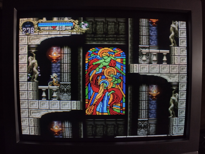
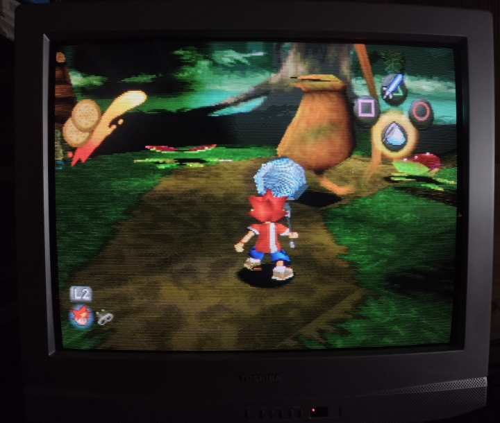
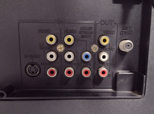
The 32A33 has a full set of inputs with composite, S-Video, and component video. Picture quality with component video is very clean, and geometry is excellent.
Literature
Notes
This TV uses the same chassis as two other curved screen Toshiba-made models from the same year: the 32A43 and 36A43. It differs by having speakers mounted at the bottom rather than the sides and no front AV inputs. Toshiba did not produce a separate service manual for the 32A33, instead providing a short supplement that was meant to be used with the 36A43 service manual.
Component video on these TVs is labeled "Color Stream", and shares its Y jack with the 2nd composite video input.
Unlike the Toshiba-branded Orion models, the 32A33 has menu and input select buttons on the front panel, and all functions can be accessed without having to use the remote.
RGB Mod
Written by Matt Ross (6tanks)
The TA1310N jungle chip used in these TVs has a set of dedicated RGB input pins. They are used for Picture-in-Picture in the higher end, flat-screen 32AF43 and 36AF43. The curved screen models lack the PIP feature, but the RGB pins are still activate and appear to be used for screen blanking. This means that they can be modified for direct RGB input without affecting the on screen display. The TV pictured in this guide is the Toshiba 32A33, but it should also work on the 32A43 and 36A43.
These TVs have excellent component video, and adding RGB will not provide a noticeable increase in picture quality. The benefit of this mod is that it allows the use of older consoles such as the Playstation 1, Saturn, SNES, or Genesis without requiring a transcoder.
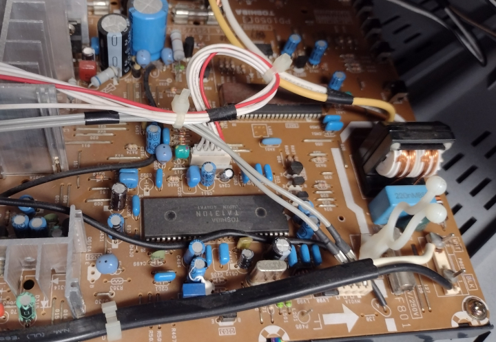
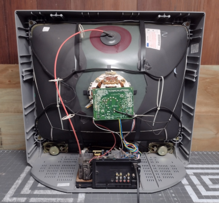
On this chassis, the jungle chip is labeled Q501 and is located near the front of the TV near the power cord. Most of the work will be done in this section and near the A/V port.
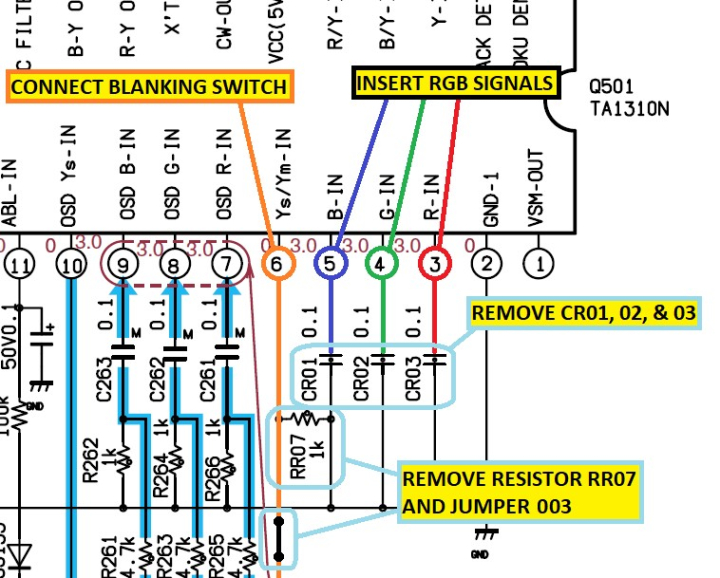
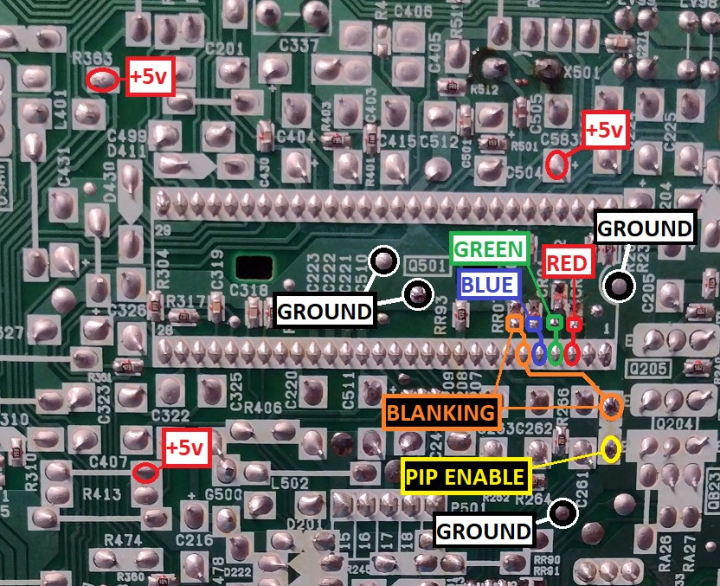
As can be seen in the service manual, the RGB inputs are located on pins 3, 4, and 5 of the jungle chip, and blanking is on pin 6.
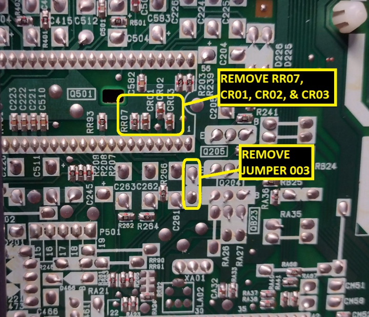
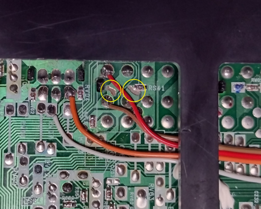
The RGB and blanking pins must be isolated by removing capacitors CR01, CR02, and CR03, resistor RR07, and jumper 003:
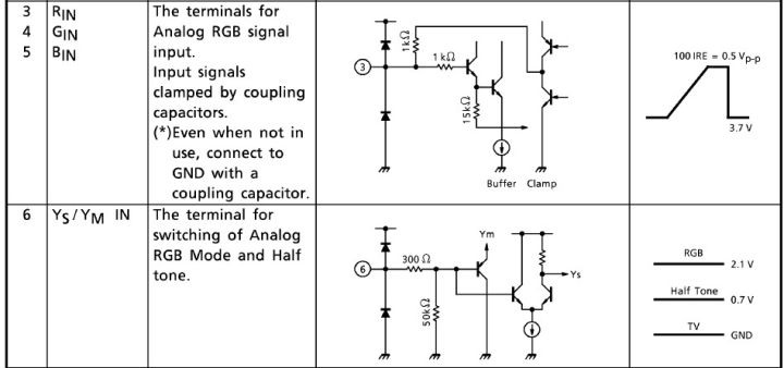
As detailed in its data sheet, the TA1310N uses a voltage level of 0.5 Vpp for the RGB signals. This is lower than the standard 0.7 Vpp, and the picture will be too bright if the usual 75 ohm termination is used. For blanking, switching to RGB requires a minimum of 2.1 volts.
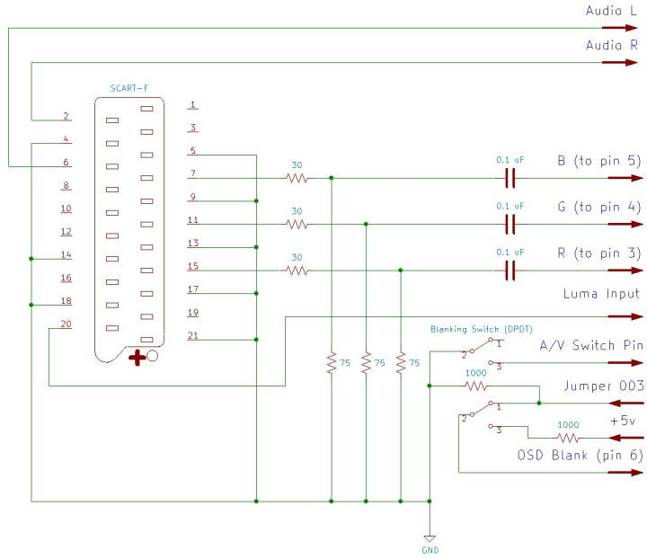
To bring the RGB signals down to the required 0.5 volts, 30 ohm inline resistors can be added to the inputs, followed by 75 ohm terminating resistors to ground. Another option would be to use a 24 ohm inline resistor and a 51 ohm resistors to ground, which would be a more "correct" method since it provides a total of 75 resistance. In practice, either method should work. 0.1 uF coupling capacitors must then be added before connecting the RGB lines to the chassis.
Sync (ideally in the form of composite video or luma) should be connected to the Luma pin of the S-Video input, as the comb filter used by the composite inputs will cause excessive horizontal shift in the picture. To enable the S-Video input for sync, there is a pin on the S-Video port that must be connected to ground. This can be wired in tandem with blanking if a DPDT switch is used, or hard wired if the composite input is no longer needed.
Blanking can be connected to a +5v supply via a 1000 ohm resistor on one side of a double throw switch. The other side of the switch can be connected to the micon side of jumper 003, which will restore its original function when RGB is disabled.
If using a SCART connector, wire it up as follows:
Attachment points for RGB, blanking, ground, and +5v can all be found near the jungle chip:
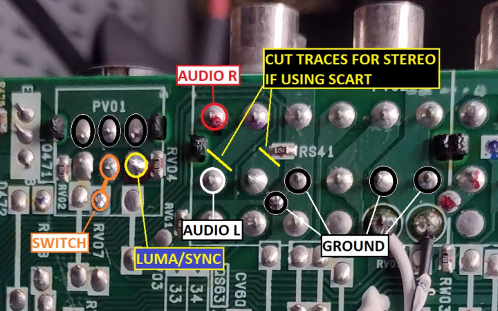
Audio signals, Sync, and the S-Video switch can be routed to the bottom of the AV input connectors. If using SCART or another connector type with integrated audio, there are two traces that should be cut in order to enable stereo sound (this is not required if the original audio jacks are used).
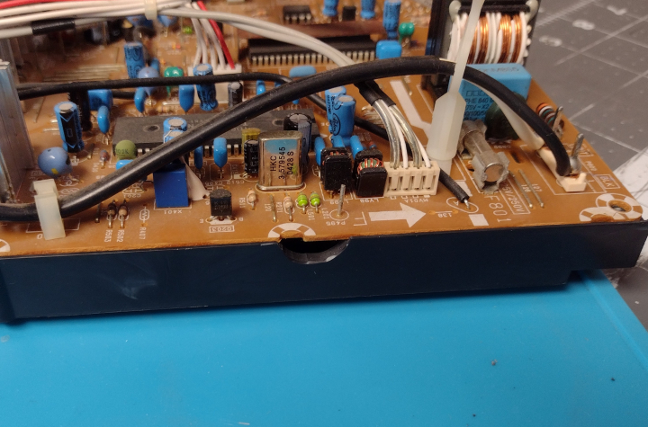
To provide a path to route the wiring from the bottom of the board, I used a Dremel tool to cut small gaps in the board in two areas:
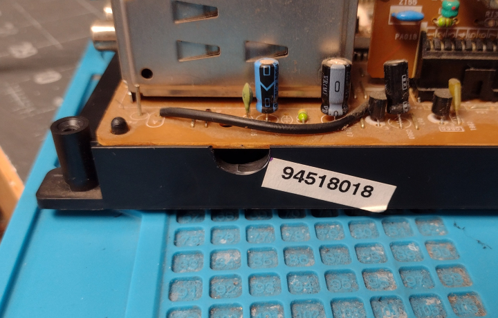
Before connecting RGB and blanking, a 1000 ohm resistor can be added between the micon side of jumper 003 and ground. This serves as a replacement for RR07. This point can be connected to the other side of the blanking switch so that when RGB is disabled, the TV's original configuration will be retained.
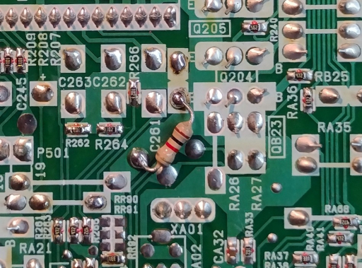
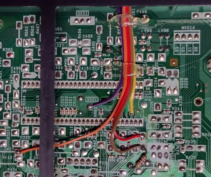
I used 26 gauge ribbon cable for wiring, secured with a bead of hot glue and routed off the side of the PCB.
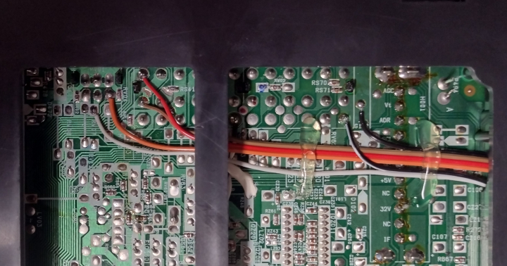
Before connecting the audio pins, I cut the two traces necessary for stereo sound using a small dremel bit.
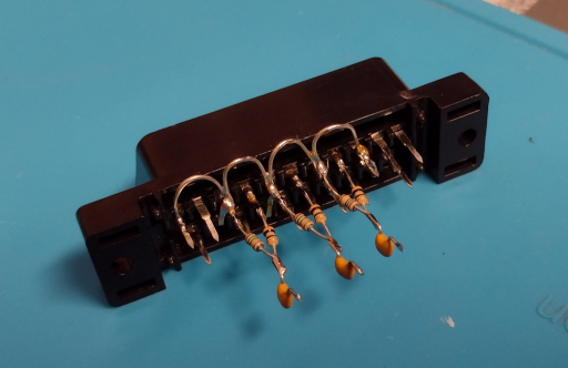
The SCART connector is wired up with all ground pins connected together, 30 & 75 ohm resistors installed, and 0.1 uF capacitors inline with the RGB leads. It can be mounted horizontally above the AV inputs. For more information, visit the SCART installation guide.
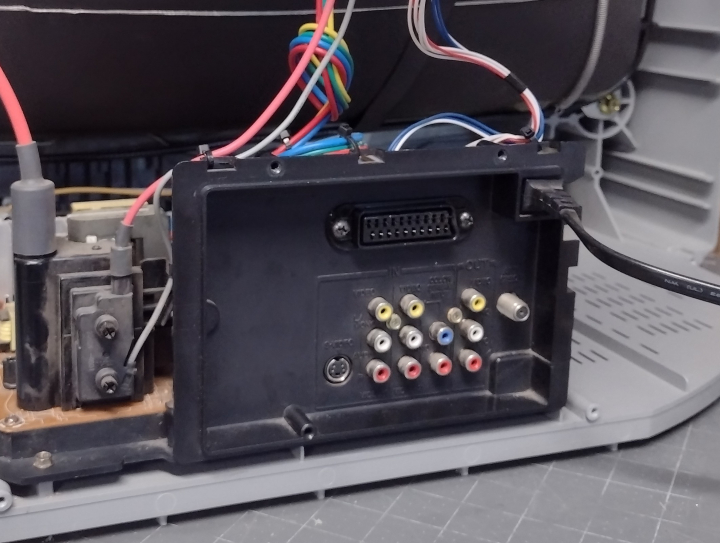
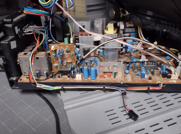
I drilled 3 sets of parallel holes along the edge of the chassis frame, which allowed me to secure the wires with zip ties and run them neatly up the side of the chassis to the rear panel. Wires for blanking and S-Video select were routed to a small quick connect.
The S-Video mode switch and blanking are connected to a DPDT toggle switch, with the 1000 ohm resistor attached to the 5v line. The switch can be mounted in the left front corner of the TV for easy access.
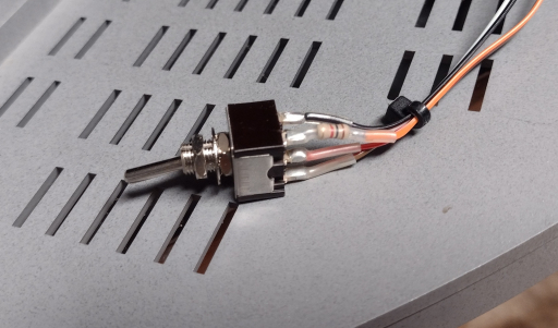
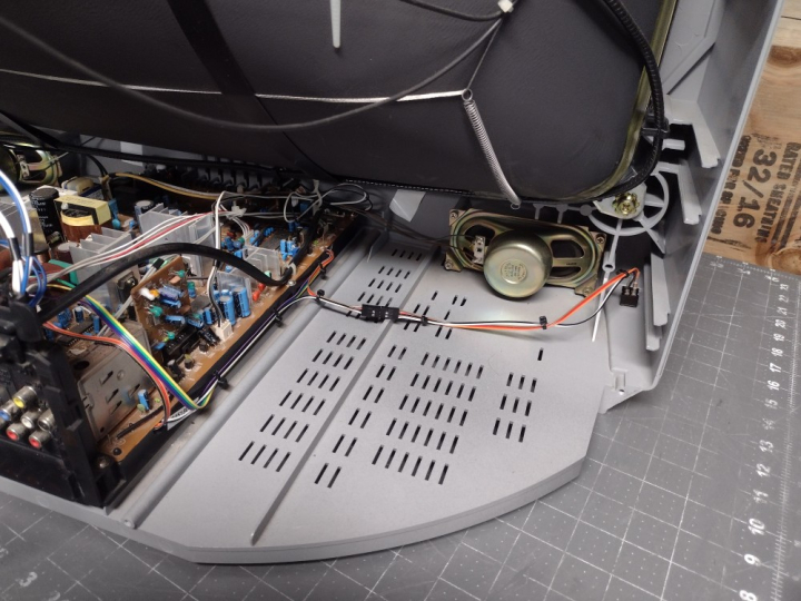
With the TV's case reassembled, the SCART port and blanking switch are neatly mounted and accessible, making it easy to switch between YPbPr/Composite on Video 2 and RGB on Video 1. However, because the RGB mod uses the S-Video input for sync, RGB and S-Video cables should not be connected at the same time.
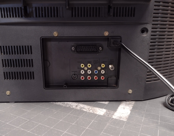
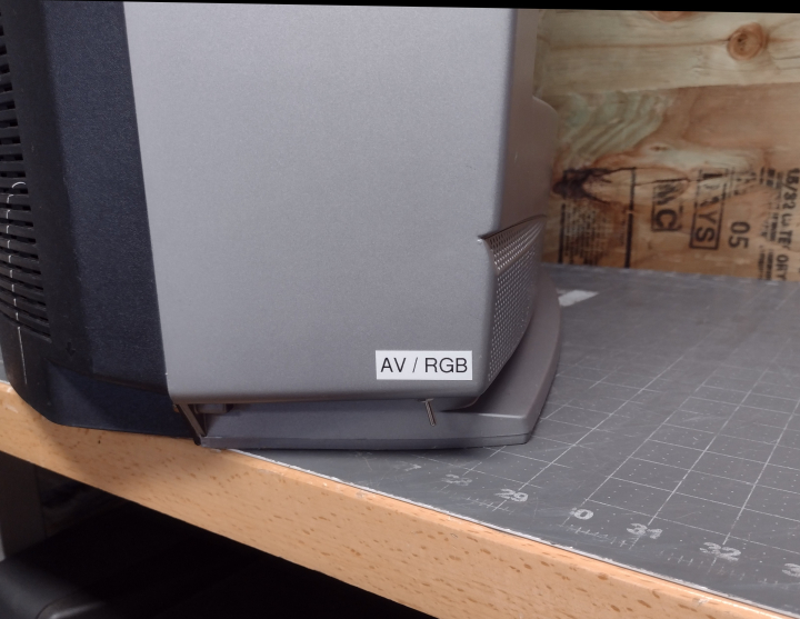
Now that the mod is done, the TV will display a clean RGB image when the blanking switch is enabled and the TV is set to Video 1. The picture may be shifted horizontally slightly. To compensate for this, refer to the service manual and adjust HPOS so that the image is centered. If you plan to use component video as well as RGB, it may be best to set a compromise between the two since they won't line up exactly.
When in RGB mode, contrast levels will match the other inputs and can be adjusted in the user menu. However, the brightness setting for RGB is controlled separately. To set black levels for RGB, enter the service menu and adjust "RGBB".
Gallery





 This work is licensed under a