JVM TM-H1700G RGB Mod
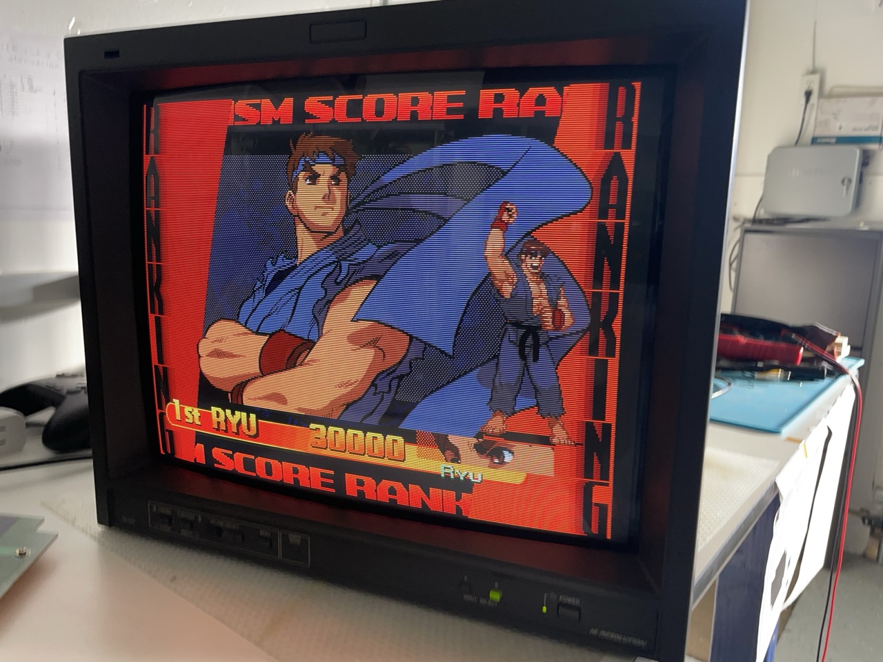 The TM-H1700G is a very nice professional monitor made by JVC; it has a beautiful 16" dot-mask tube, super sharp with 750TVL. More information can be found here.
The 1700 only has composite and s-video inputs, but it's possible to rgb-mod it. There is a variation of this monitor called H1750G that has RGB inputs, and the 1700 has most of the same components so we will leverage that.
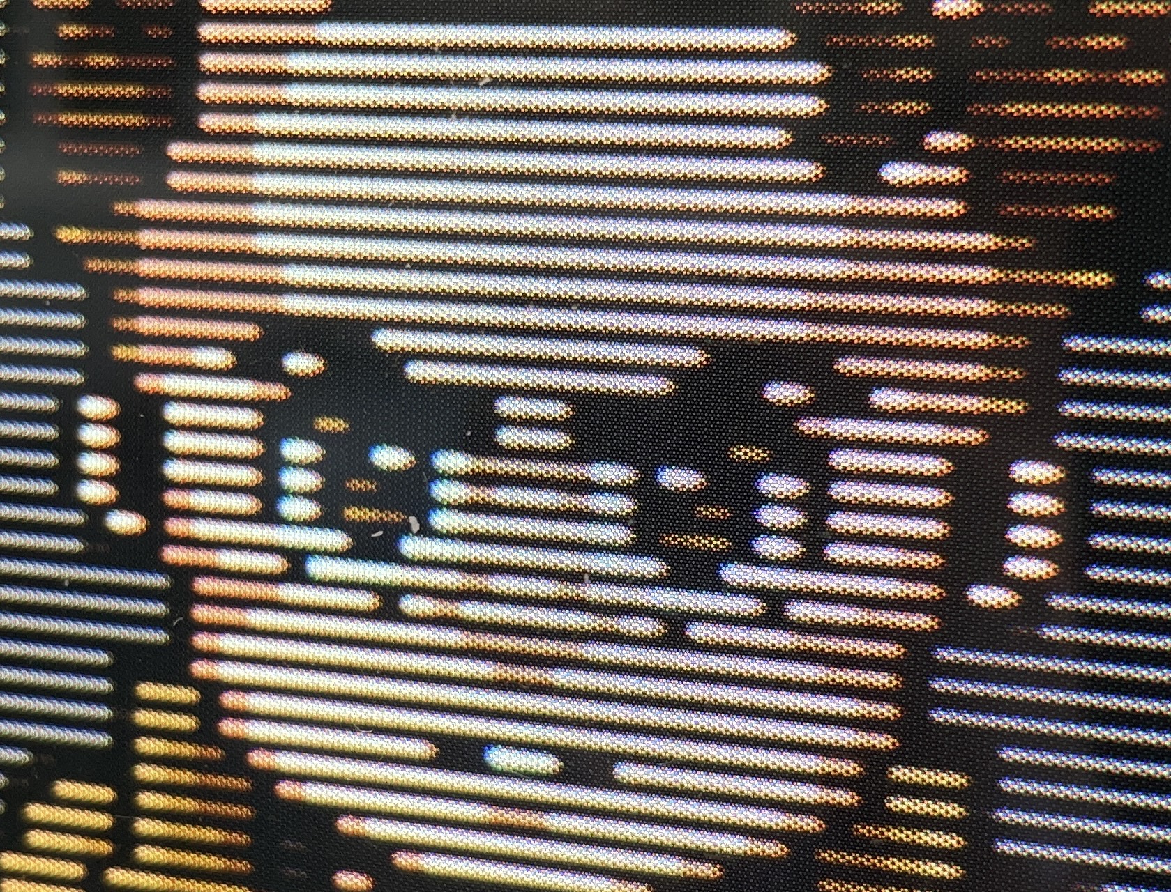
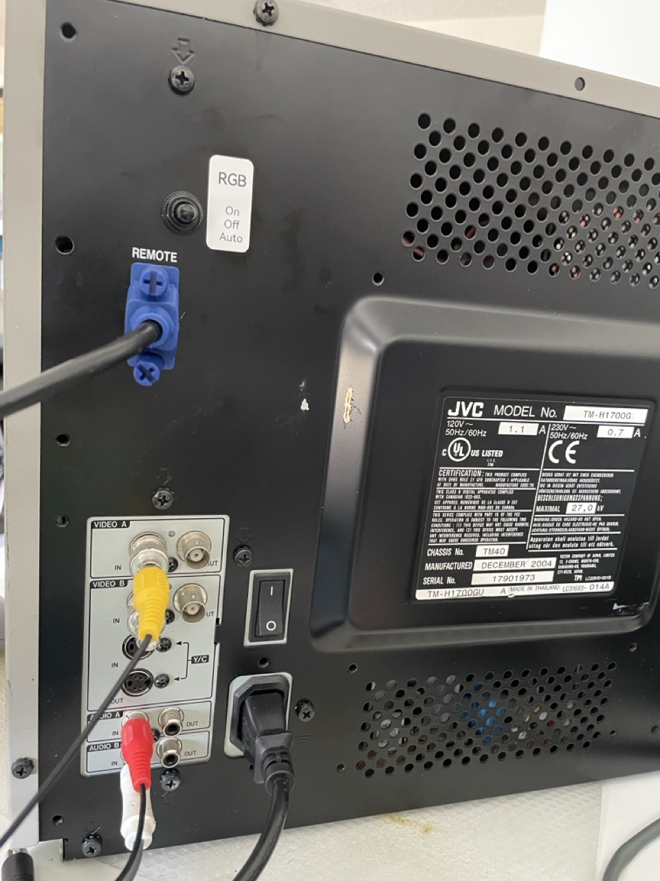
In this mod we will also reuse the DE15 connector for the remote as a VGA input, so we keep the rear panel very clean and it will look stock.
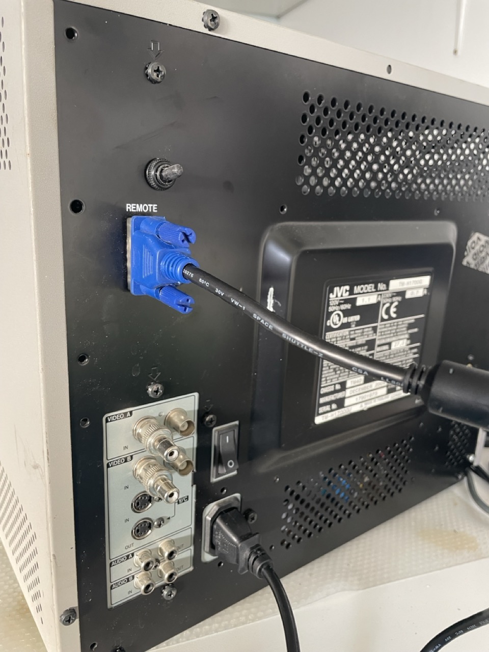
The TM-H19XX have the same chassis and the same mod can be used for those as well.
Theory
Preparing the Signal Input Board
This monitor uses a Toshiba TA1276AN Chroma chip. This chip has 2 sets of analog RGB inputs: one is used for the OSD menu, and the other set for the RGB inputs in the H1750, H1950 and the versions with expansion slots on the back.
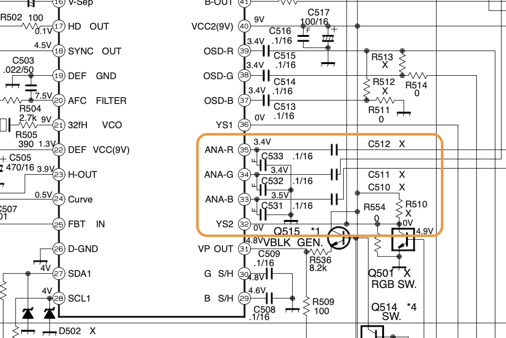
For the mod we will use pins 35, 34, 33 for R, G, B signals and pin 32 for blanking.
On the "Signal Input PWB" board we need to:
- remove R554 to disconnect blanking from ground
- (optional) remove C531, C532, C533: you can keep them but image will be slightly sharper without
- connect the R, G, B cables on the unpopulated pads for C512, C511, C510
- connect the blanking cable to the left pad of R554
- connect the ground cable to one of the legs of W276 (or any other ground plane nearby)
The following picture shows the board before/after:
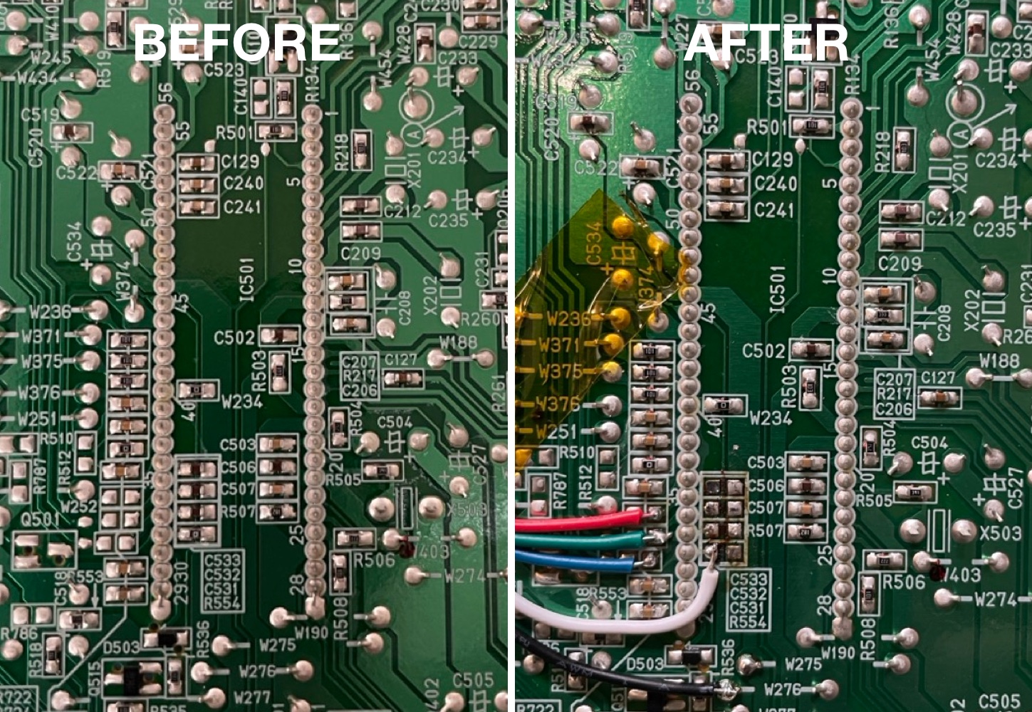
Circuit to inject RGB signal
The chroma chip does not use the standard 0.7 Vpp voltage, but instead expects 0.5 Vpp, as can be seen in the datasheet:
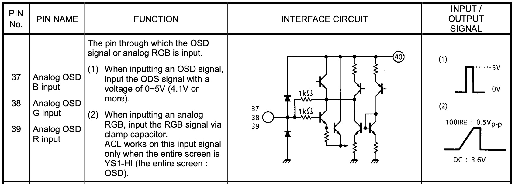
So we need to adjust the input voltage, and at the same time keep the input termination as close as possible to the standard 75 Ohm. The following circuit shows the voltage divider circuit I used:
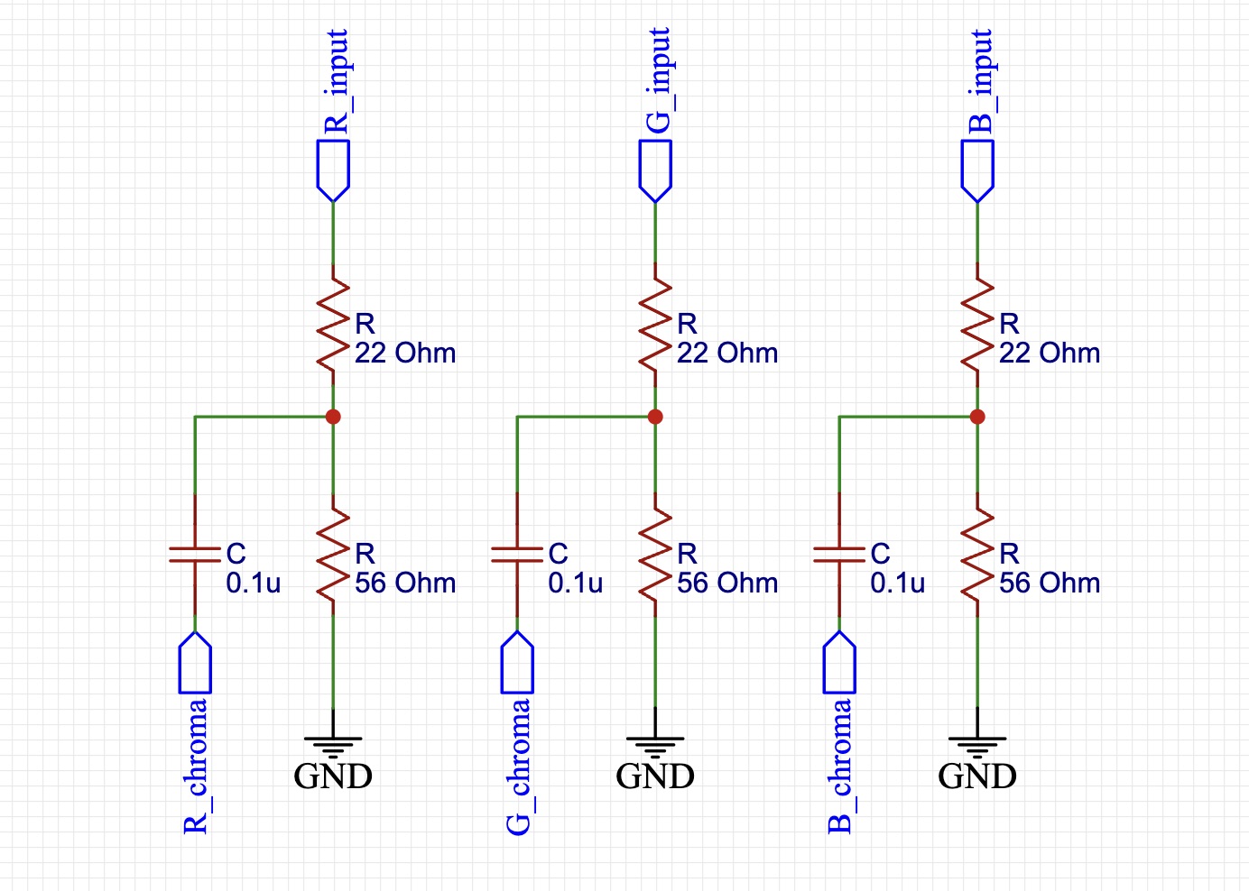
As you can see the termination is 78 Ohm (56 + 22), and the voltage divider will bring down the input signal to 56/(56+22)*0.7 = 0.5 V which is exactly what is expected by the Chroma.
I created the circuit above using my rgb-mux board:
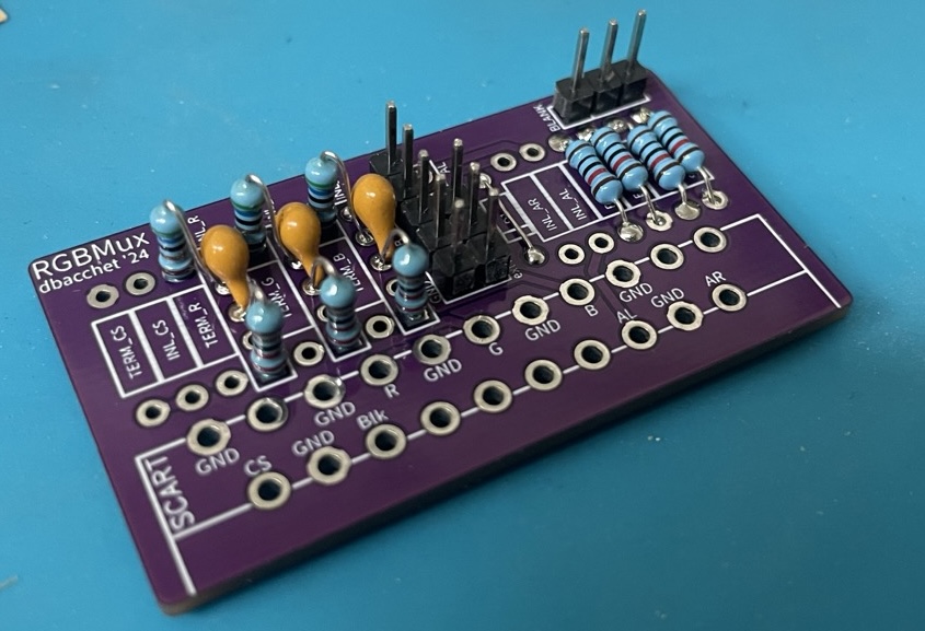
I use this board with SCART mods, but the signals are exactly the same so it was very convenient.
On the right there are 2 voltage dividers (all four resistors are 10k Ohm) used for blanking: they will bring down the 5V voltage form the board or from the VGA (pin 9) to ~2.5V that is enough to trigger blanking in the Chroma. I connected those on a DPST switch with 3 positions:
- On: RGB input is forced On
- On: RGB input is disabled
- Auto: RGB input is triggered when the device connected to VGA is on
The two sources used for 5V are the jumper W034 (5V rail) and pin 9 of the VGA connector.
Sync
The last thing that we need in order to have a stable image is to pass the c-sync signal. To reduce the lateral shift of the image between composite and RGB to the minimum we can use s-video because it does not go through the comb filter. What we need to do in this case is to wire the c-sync signal from the VGA (or your input RCA connector) to the pin 3 of the s-video connector.
Use the Remote DE15 connector as input
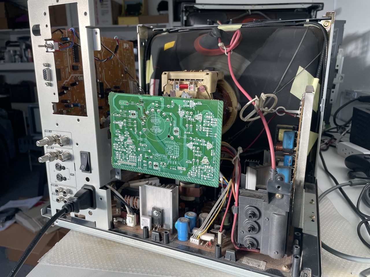
The remote DE15 connector can be used as input with a standard VGA cable. First we need to isolate the connector pins from the rest of the remote logic:
- remove the K004, K003 inductors
- remove the diodes D001, D002, D003, D004, D006, D007, D008, D010, D011, D012, D013, D015, D016, D017, D018
- remove the resistors R001, R002, R003, R004, R006, R007, R008, R009
- disconnect pin15 from ground removing the jumper W015
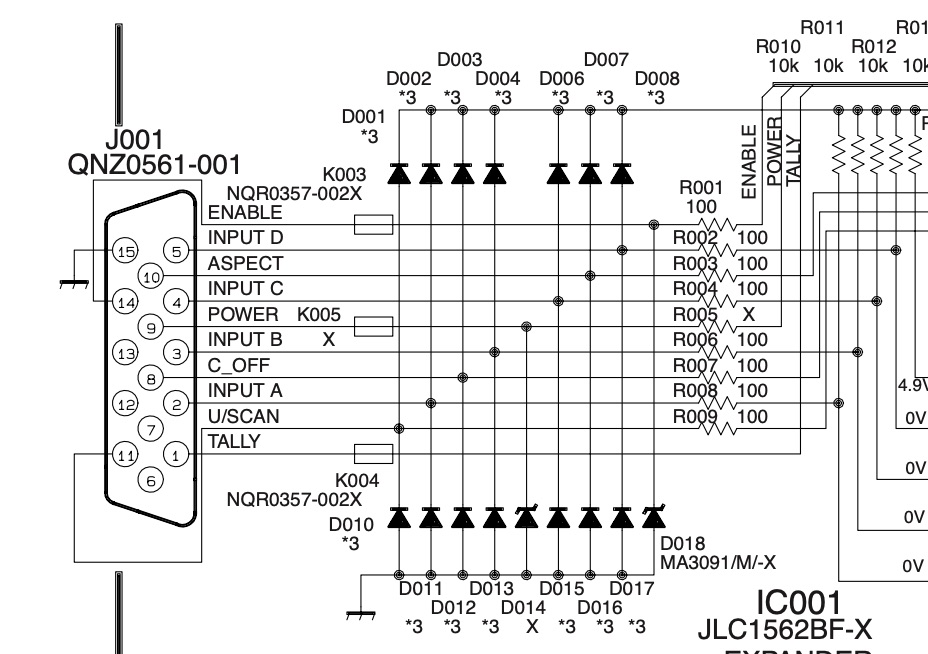
And after that wire:
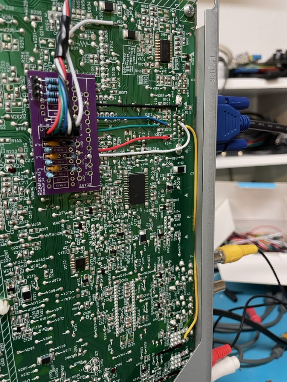
- pin 1, 2, 3 to the R, G, B inputs in the mux board
- pin 9 to the 5V input of the mux board
- pin 13 to pin 3 of the s-video connector for sync
- pin 5, 6, 7, 8, 10 to ground
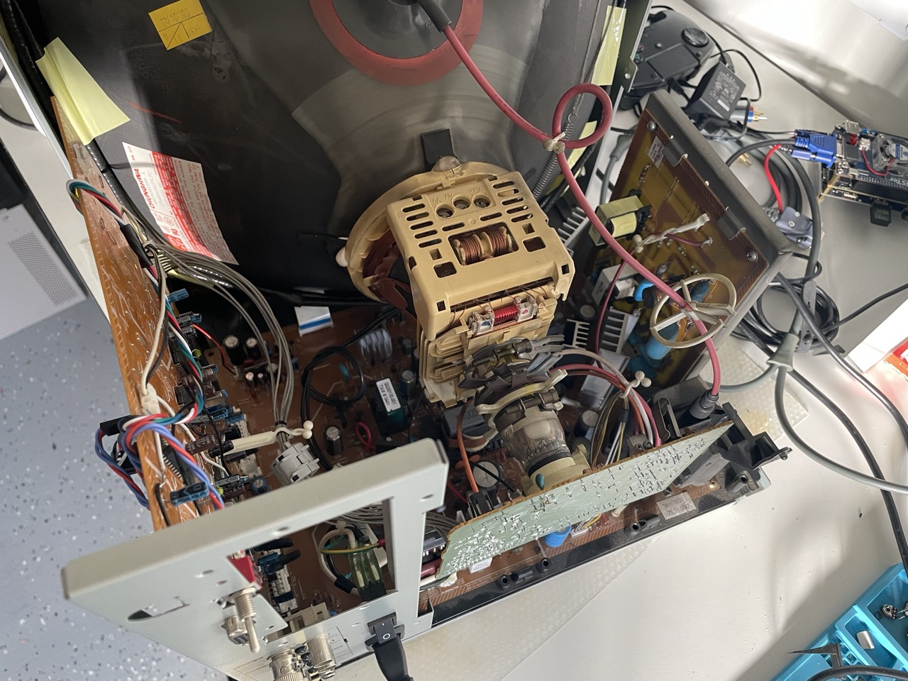
The following image shows the mux board installed and wired to the VGA connector:
Select the right sync source when on RGB
With the modifications above, we are basically ready to have a stable image in RGB when using Video B input, and we only need to make sure that the monitor is correctly using s-video for sync and not composite.
However if you want to test your work at this stage, don't be surprised if you don't see any image onscreen. You need to plug an s-video connector in to activate the sync processing (doesn't need to be connected to anything, the plug is physically switched/activated by inserting a cable) and you also need to bridge the "BLANK" and either "EXT" or "SCART" pads in the upper corner of the mux board to enable blanking. Later we will wire a switch to these pads. If you bridge EXT then blanking will always be enabled if 5v is connected to "extVCC" on the mux board. If you bridge to SCART then blanking will only be enabled if your source device is providing 5v via pin 9 of the VGA connector.
To continue on with the mod after testing, there are 3 options here we can consider:
- keep a s-video connector plugged in to the Video B input whenever you want to use RGB mode (which means you won't lose your second composite input and can also can skip making the switching circuit below)
- remove jumper W306, that always forces Video B to s-video (in this case composite can only be used on Video A and you can skip making the switching circuit below)
- implement a circuit to inject the right logic when we are using RGB (which means you can keep both composite inputs and lose no factory functionality with the mod)
Circuit
The s-video selector is pin49 on the IC701 chip: there is a pull-up resistor that keeps that pin high and it is also wired to pin 9 of the s-video connector. When the plug is disconnected, pin 9 goes to ground and IC701 commutes to composite. That rail goes through the jumper W306, that is where we will work. To keep the original functionality (both composite and s-video usable on Video B) and support RGB, we need a circuit that:
- keeps W306 closed when we are not using RGB
- opens W306 when we are using RGB
The circuit is actually fairly simple:
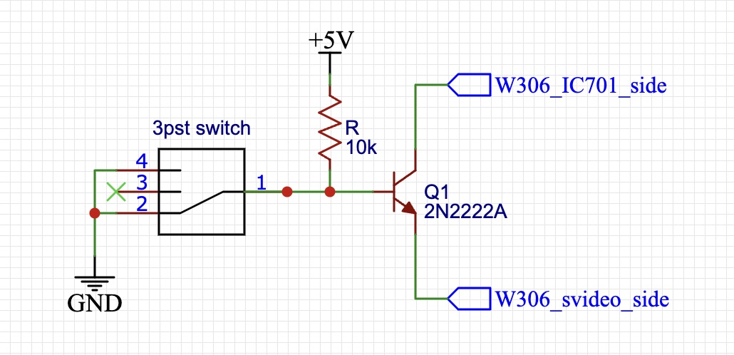
Here the transistor acts as a switch, and we control the gate through the same DPDT switch we are using to commute On/Off/Auto.
The small PCB installed on the board:
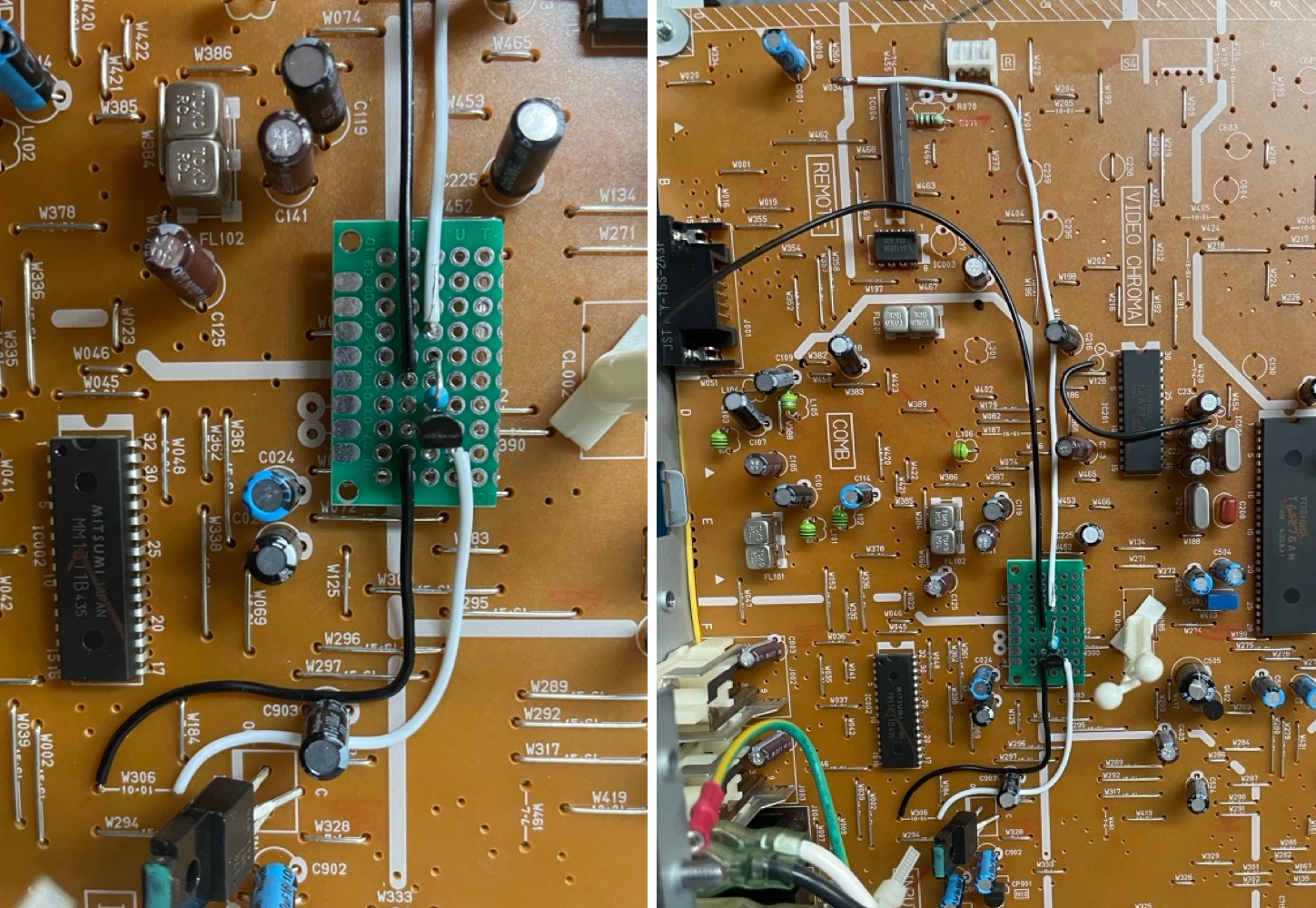
And with this we are done!
Pictures
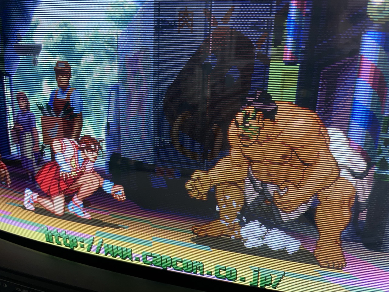
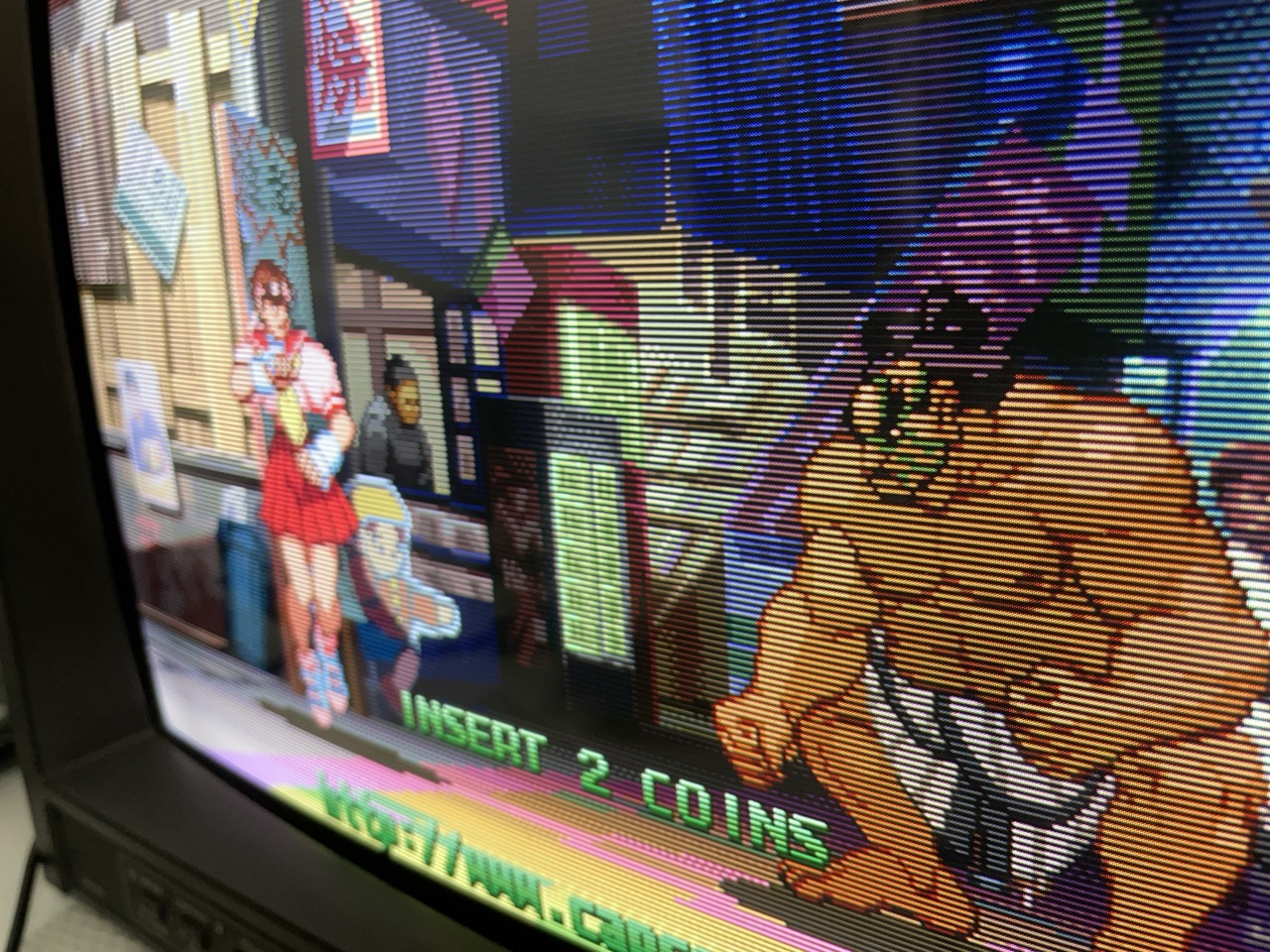
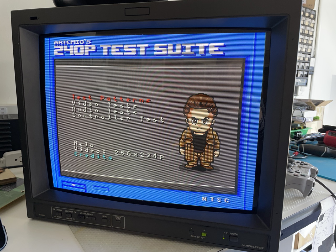
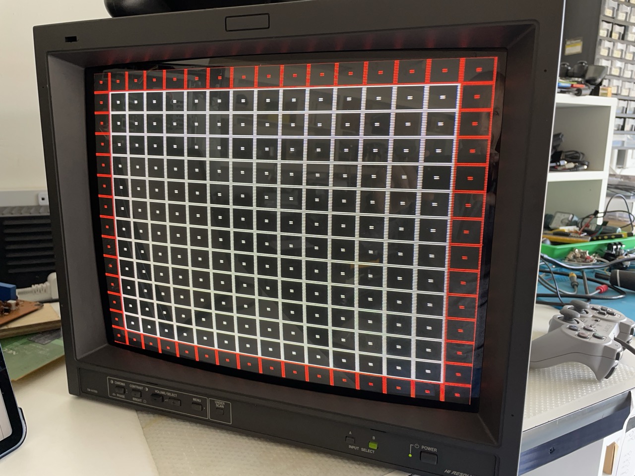
Let's conclude with a few pictures showing the TV and the image quality:


 This work is licensed under a