KV-13FM12 / 13 / 14 MultiMod
A while ago, while helping a friend to mod their 13FM12, I had the idea of adding all possible inputs to this little tv, and enable them through the remote. The main reason, honestly, was to experiment and learn by doing a nice project, so when the same TV showed up at our local e-waste center I just grabbed it and started this journey...
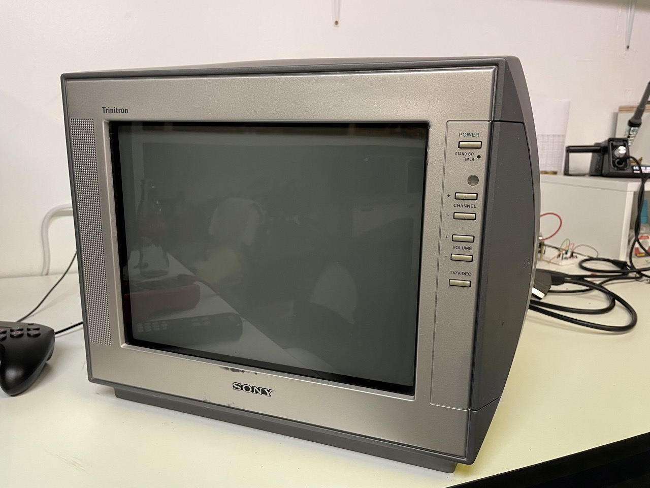
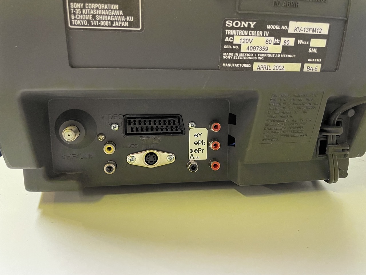
This TV ordinarily has RF and two composite inputs, one in the back and one in the front; at the end it will have:
- RGB with a SCART connector
- Component with Y/Pb/Pr RCA connectors
- S-video
- commuting between RF, RGB and component using the remote (and not a physical switch)
Let's get started...
The 13FM12 has a BA5 chassis, so for RGB the standard mux mod works; for a detailed explanation you can check this article on CRTDatabase, or my previous Reddit post about a KV-24FV12
RGB Mux
The entire mod can be done in the MB board; start by removing the grounding resistors R1084, R1085, R1086:
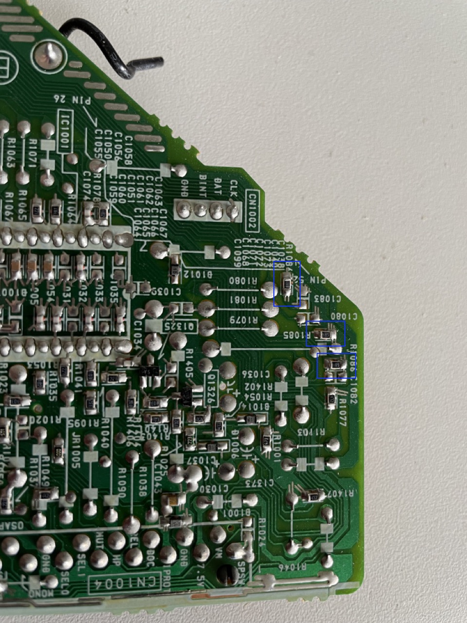
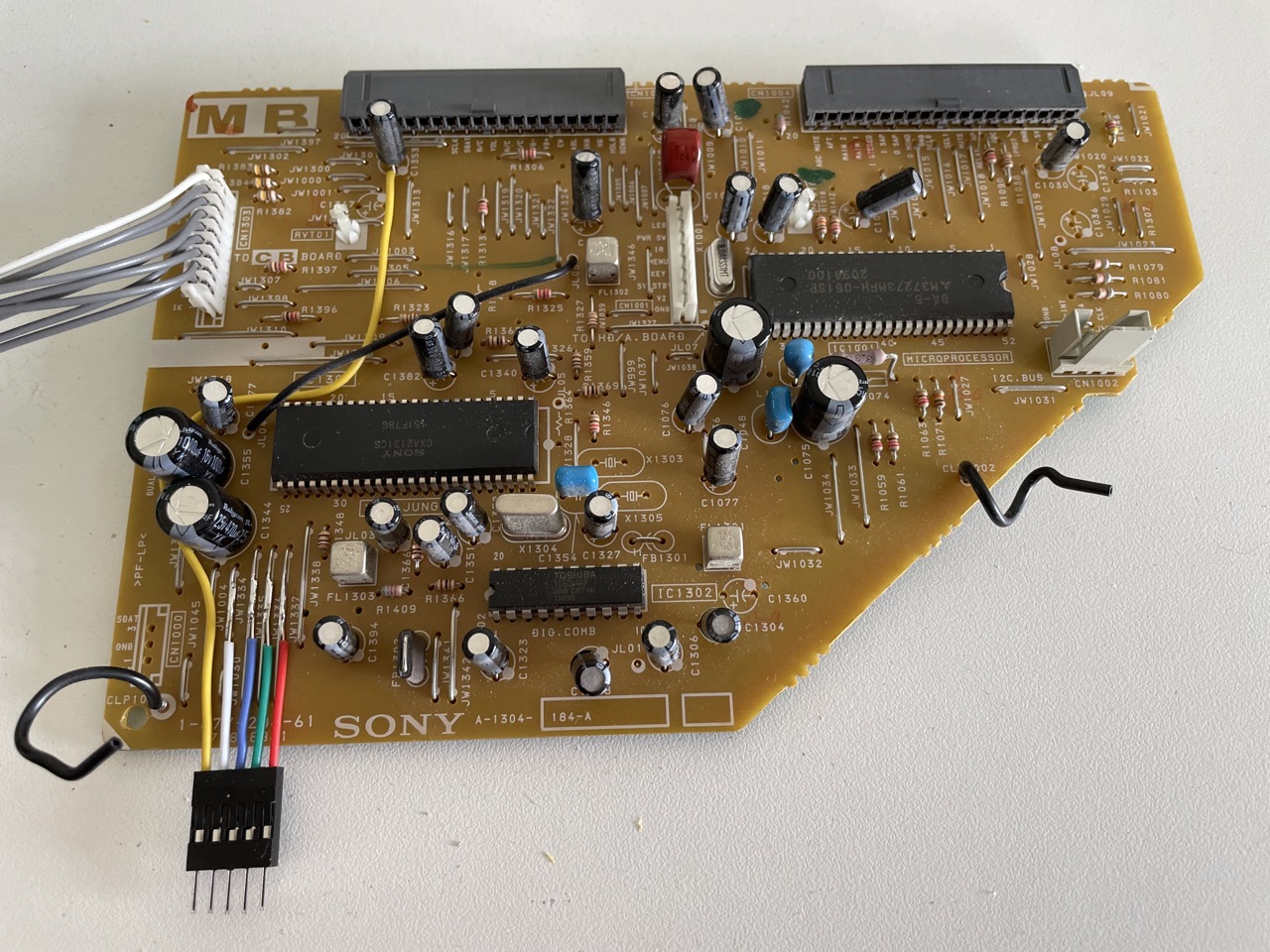
The R,G,B signals can be injected in the jumper wires JW1337 ( R), JW1336 (G), JW1335 (B), and the blanking signal Ys to JW1334.
I chose to use Video1 for the RGB sync, and injected the signal to the negative leg of C1353. This is not ideal, as there is a lot of left shift in the image, more than what can be corrected with the service menu. The best solution is to inject the sync after the comb filter, and we will fix that later in the "Preventing image shift" section.
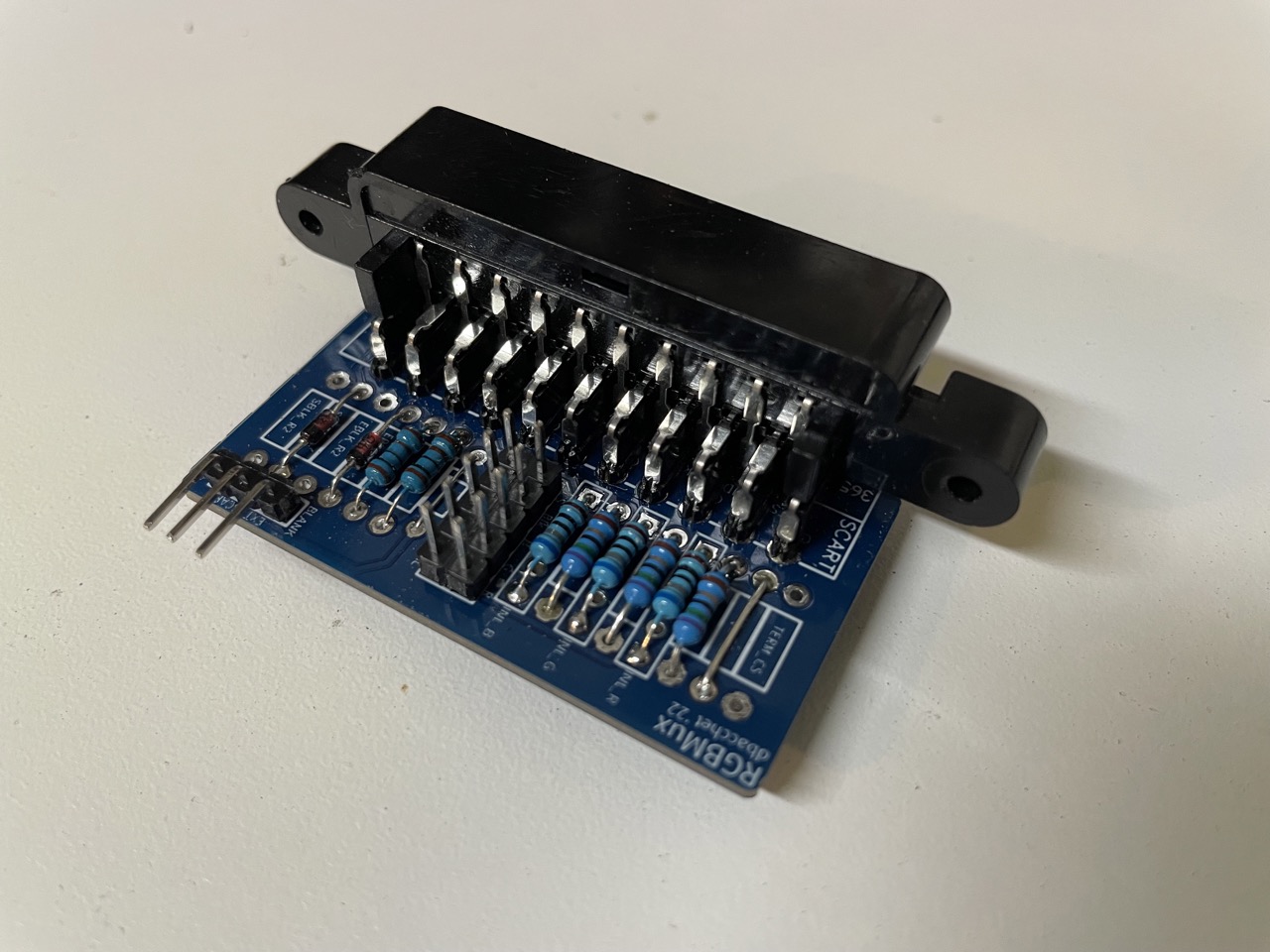
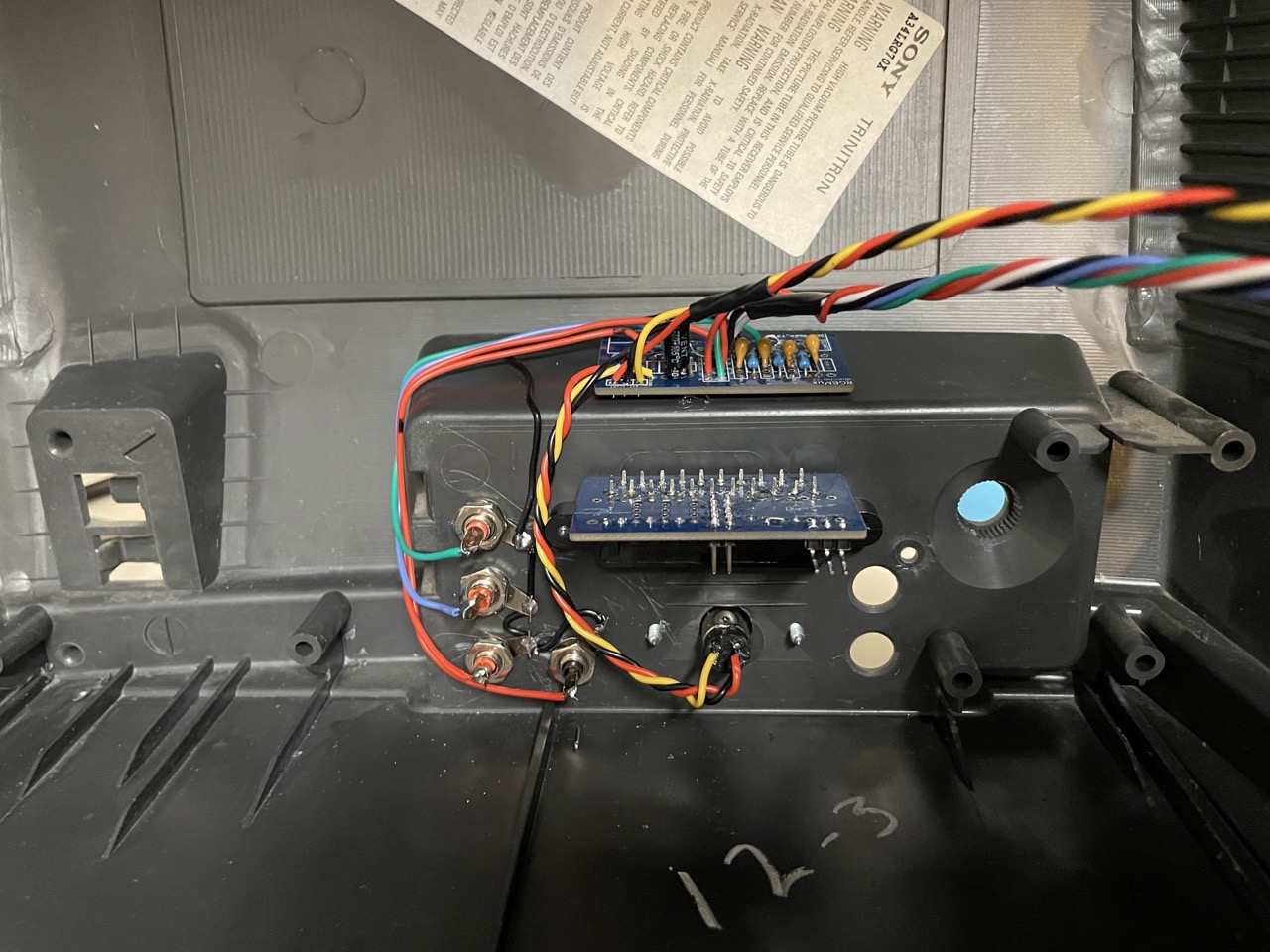
I used my SCART mod board to simplify the wiring. You can see that there are 75 Ohm termination resistors and 680 Ohm inline resistors on the R,G,B lines.
RGB Audio
Since we are using Video1 for RGB, we need to connect the SCART audio to the right place. In this case, the most convenient place to inject the signal is the negative pole of C208 (close to the existing RCA connectors in the A board).
Component
The chroma chip accepts Y, Pr and Pb at the pins 37, 38, 39, and enables Component input through the YUVSW signal at pin 36.
The first thing to do is to remove the existing grounding capacitors C1345, C1349, C1350:
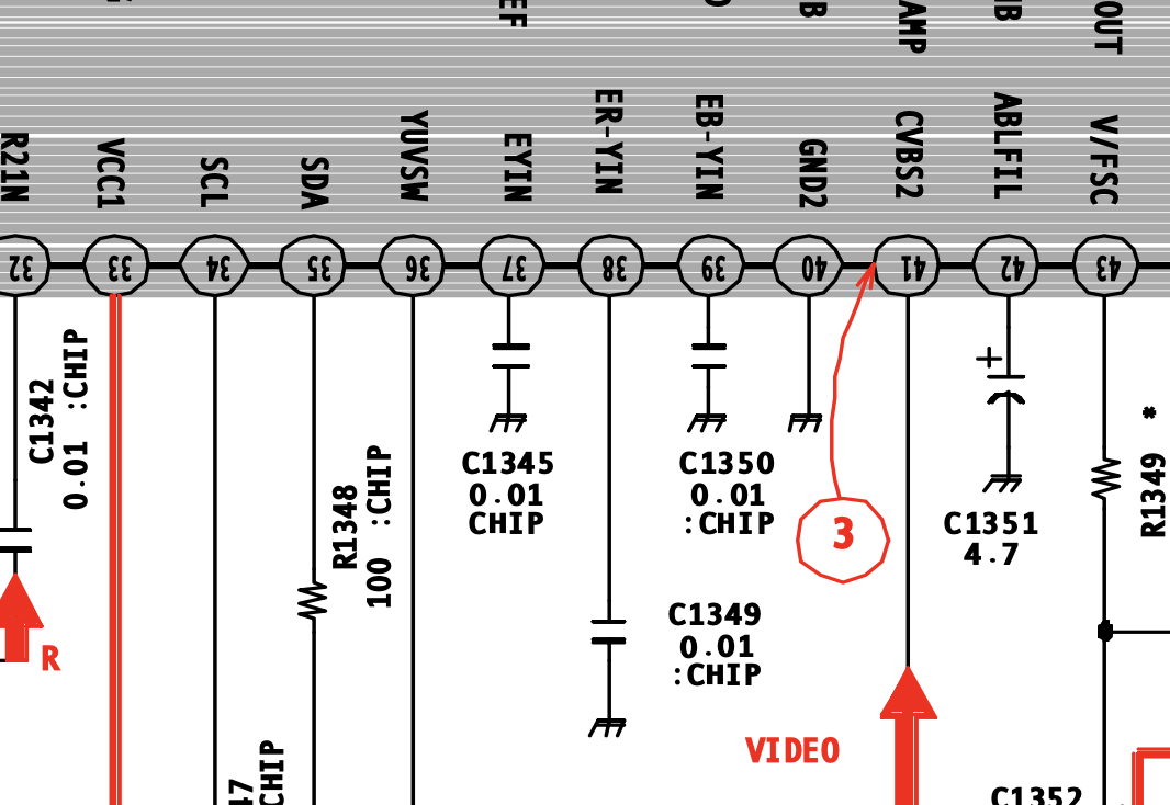
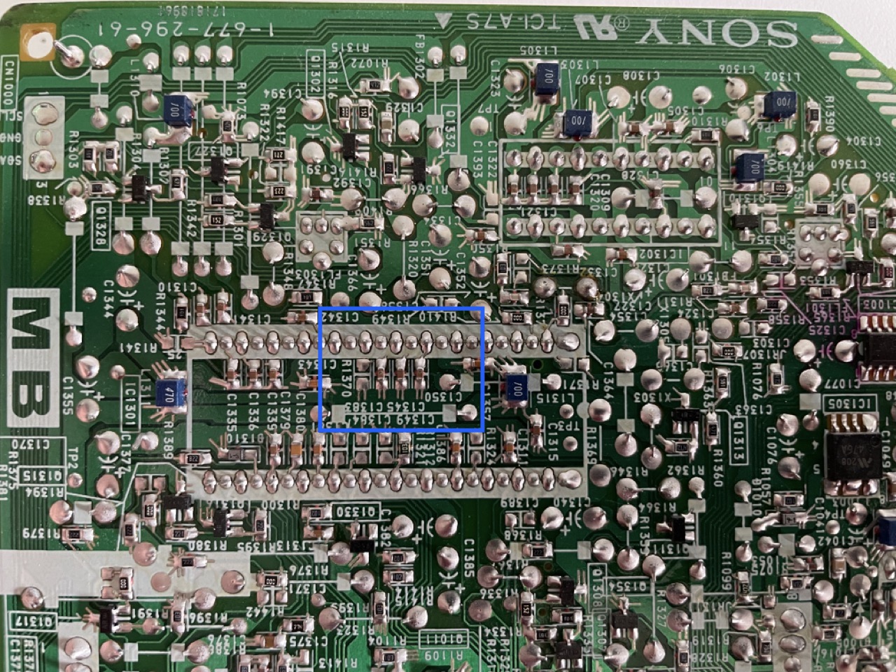
Then what we need to do is to inject Y, Pb, Pr to the same pins, using 0.1uF coupling transistors and terminating each signal with 75 Ohm resistors. The Y cable has to be also connected to the Sync input (after termination and with another 0.1uF cap), and since I chose to use Video2 for the Component sync, that corresponded to the front RCA connector. This will generate too much shift in the image, same problem we have with the RGB mod. See the "Preventing image shift" section below for the solution we implemented.
Component Audio
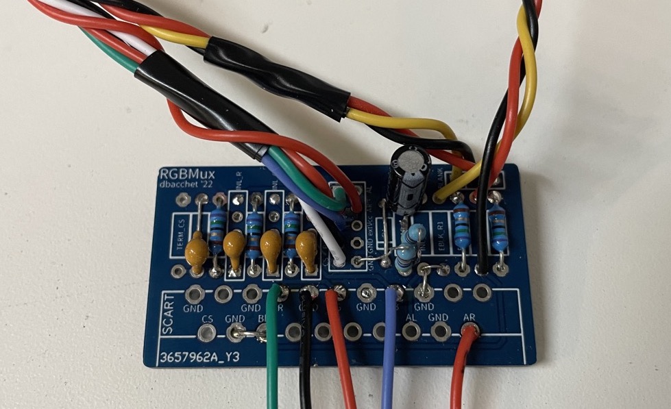
There are two options here; we can either wire the audio signal to the front video2 connector on the HD board and inject on R2216/R2215 or we can recreate the small circuit with the grounding resistor and the capacitor, and inject at the jumper wire JW250 in the A board (close to the existing RCA connector). I decided to go that route so I added a 470k Ohms ground resistor, a 4.7k Ohm inline resistor and a 4.7uF cap to the small PCB I used for the other components needed for YPbPr. For injection, another excellent point is the unpopulated connector CN460, pin 19.
The following picture shows the breakout board I used for the Y,Pb,Pr and audio signals.
S-video
I also wanted to add s-video, because... well, why not! At the end of the day the main purpose of this project was to experiment and learn...
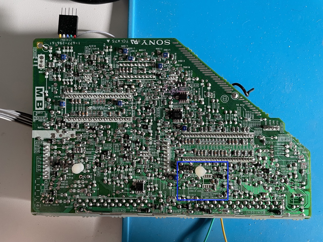
The chroma chip can take luma and chroma from the comb filter on pins 9 and 7, that are used for all the input sources, independently from which channel is selected. But there are also 2 additional pins (4 and 2) that are used in other BA5 sets for s-video on Video1. In order to use the additional s-video input on this set is not enough to just hook Y and C to the chroma, unfortunately. Looking at the schematics of another set with the same chassis and s-video (for example the KV-20FS12), C can be injected directly to the chroma, but Y goes to both the Chroma and the Micom, using a video switch IC that is missing on the 13FM12 and has to be populated along with a few other components. The steps that need to be taken are:
- add the video switch IC1002. It's a NJM2534M, and I used one from a donor board in a broken BA5 chassis. This chip routes the h-sync to the micom from the right source.
- add the 10uF electrolytic cap C1002
- remove the jumper JR1083 to properly route the signal using the now populated switch
- add the 10uF electrolytic cap C1367 for the Y line
- add a 0.1uF ceramic cap C1389 for the C line
- inject the Y signal at the negative side of C1367
- inject the C signal at the jumper JW1320 or at R1318
- add 75 Ohm termination resistor R1317 and R1318 (or just make sure to terminate the input signals before injecting)
It's also possible to route the signals all the way up to the RCA connector on the A board, but I decided not to do it because I already had all the other wires for RGB and component coming to the MB board. If you want to do that, info can be found on this shmup thread.
Before:
After:
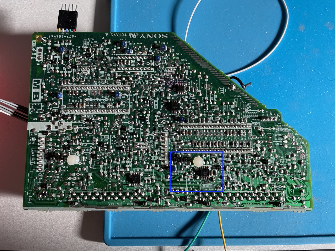
Now the last thing you need to is go into the service menu and change ID-1 from 3 to 19. This unlocks the s-video input.
Video 1 will now be used for both the rear composite and the s-video inputs, and automatically switch to s-video if connected.
Using the remote
In order to use the remote to automatically enable RGB and Component on the right channel, we will use the O-SEL0 and O-SEL1 signals (pin 10 and 11) in the Micom. They will go high (approx 3.5V) when the TV is tuned on Video1 and Video2, respectively. The idea is to use those signals to trigger YS2 for RGB (pin 29 in the chroma) when on Video 1 and YUWSW for component (pin 36 in the chroma) when on Video 2.
The problem is that connecting them directly will bring down the voltage too much on those lines and make switching of the audio/video very unstable. Using an inline 1k or 2k resistor will not work either, because then the voltage will not be high enough to activate YS and YUVSW in the chroma.
The solution in this case is to create a buffer using a transistor for each line, so we can decouple the two sides, and get ~3V to the blanking pins. The schematic is like the following:
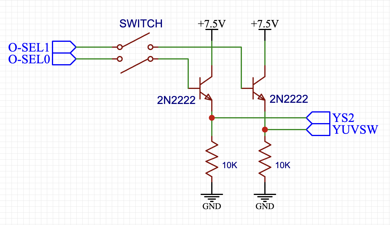
Adding a 2PST switch on the O-SEL0 and O-SEL1 lines will allow us to turn on and off the mod and still use composite on Video 1 and Video2.
The following gif shows me switching between RF, MiSTer in RGB on Video1 and a PS2 in Component on Video2:

And we are done!
But... are we?
There is still a problem we want to fix: the left shift. Injecting RGB and/or Component sync produces a left shift of the image that is usually corrected in the service menu (see the guide here for how to compensate only when in RGB). In this specific TV though, the image is also cut by the chroma so shifting alone is not enough because we will still miss a piece. Let's fix that!
Preventing image shift
To understand why the image is shifted, let's think about what happen to the composite video signal as it is processed:
- the composite video signal goes to the comb filter, that splits it into luma+sync "Y" and chroma "C". This is the same format of s-video, by the way.
- the chroma/jungle chip takes those 2 signals and extract sync info from Y
- Y and C are converted to RGB, amplified and sent to the tube, synchronized to the Sync
The list above is an oversimplification, but, well, you get the idea...
Each one of those steps introduces a small delay that is taken into account when the image is composed before being sent to the tube. The image is shifted because with the RGB/Component mods the picture information and sync signal are taking different paths:
- the sync signal is injected before the comb filter, and goes through steps 1,2,3
- the picture signal (either RGB or Component) is injected directly to the chroma/jungle chip, and goes through 2,3 only, skipping the comb filter
The picture data has less total delay and it is a little bit "ahead" of the sync signal. Since the sync is used to start each line, that is then drawn left to right, the offset between picture and sync results in the colors being sent slightly too early and the entire image will look shifted to the left.
The obvious solution is to inject the sync signal after the comb filter, and that is typically done by using the s-video Y input instead of composite, if the TV has s-video.
In our case we could use the s-video connector we just added, but then both RGB and Component will go on Video1, and we will lose the capability of switching with the remote.
But there is another solution: the chroma IC takes luma+sync from the comb filter on pin 9, and that path is used for RF, Video1 and Video2:
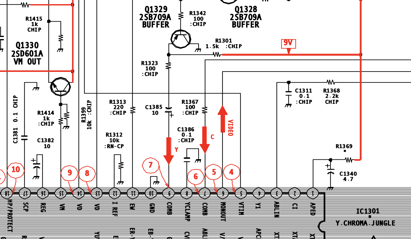 What we have to do is to inject the right signal, depending on which input is selected, and at the same time send the blank signal to YS2 or YUVSW. The following table shows the different signals:
| Source | O-SEL0 | O-SEL1 | YS2 | YUWSW | Sync |
|---|---|---|---|---|---|
| RF | 0 | 0 | Off | Off | use original (tuner, etc) |
| Video1 | 1 | 0 | On | Off | use RGB sync |
| Video2 | 0 | 1 | Off | On | use Component sync |
C1385 provides a very convenient injection point: if we remove it we can get the original Y signal from the negative pole, and inject our selected sync to the positive pole.
We can use a mux IC like the CD4052 to select which input to pass function of the values of O-SEL0 and O-SEL1, exactly like in the table above. Since the CD4052 has 2 sets of inputs/outputs, we can also use it for the blanking signals YS2 and YUVSW, removing the need to use the buffers.
The following schematics show the circuit:
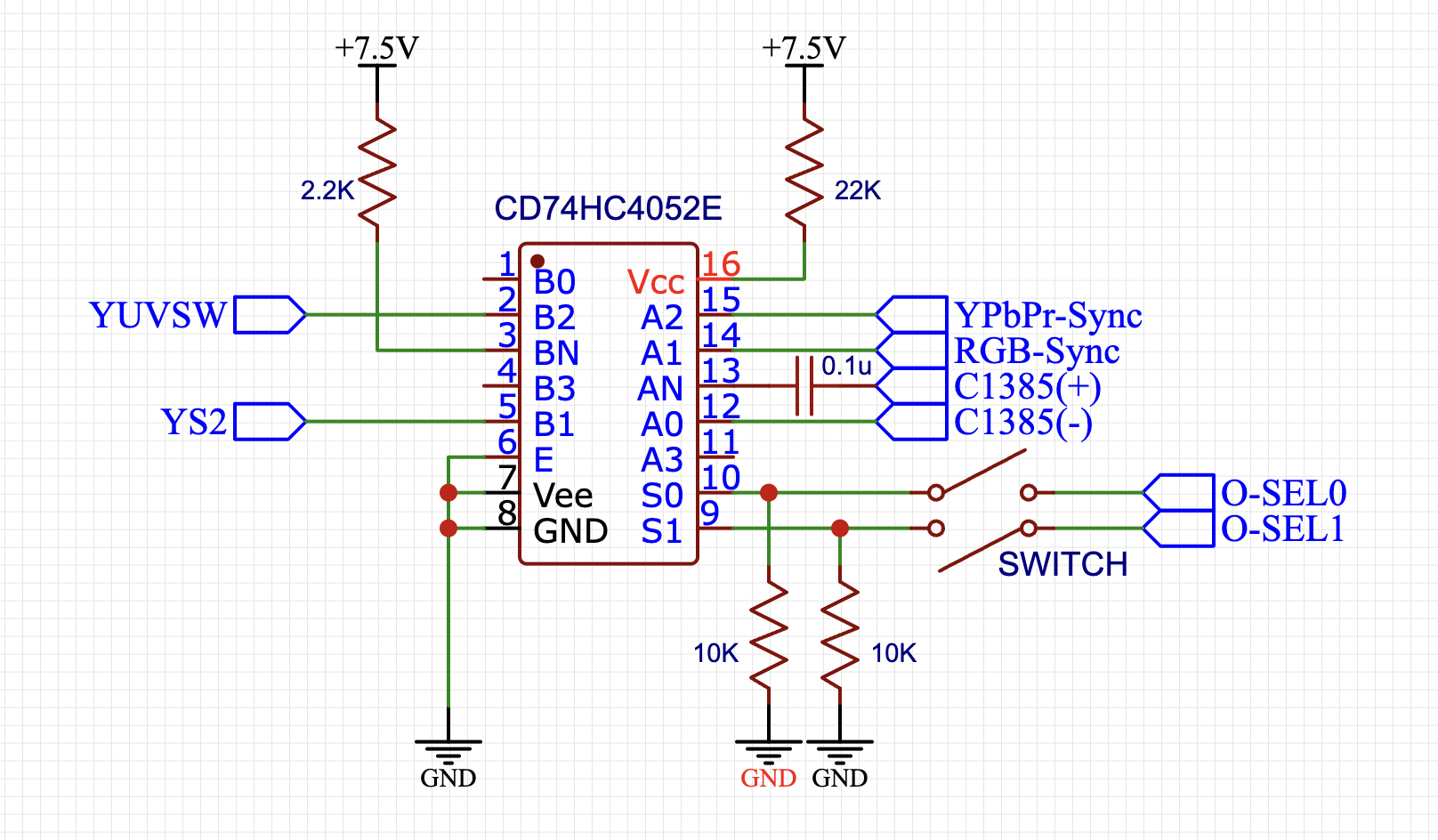
The three sync sources are connected to pins 12 (original sync), 14 (RGB) and 15 (Component), and the output goes on pin 13; we added a 0.1uF coupling cap to replace C1385 that has been removed. On the other side a fixed voltage is applied to pin 3, and routed to pin 5 (YS) or 2 (YUVSW). A 2PST switch is used to enable/disable the mod: when the switch is off, the pull-down resistors drive the selector pins S0 and S1 to low, that select the original inputs.
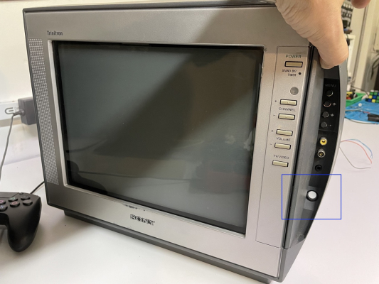
In my particular case I went one step forward: I wanted to use a SPST push button hidden in the front panel to enable disable the mod, this way I have a very convenient access to the button and it is also hidden behind the panel door.
We can use another CD4052 as a global switch to replace the 2PST, extending the previous circuit like in the following schematic:
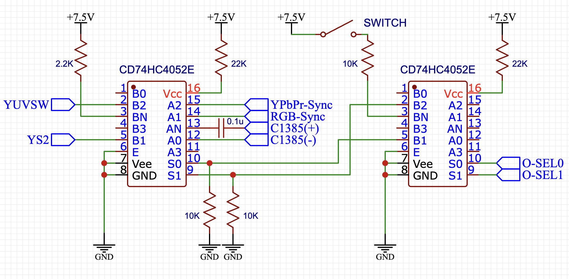
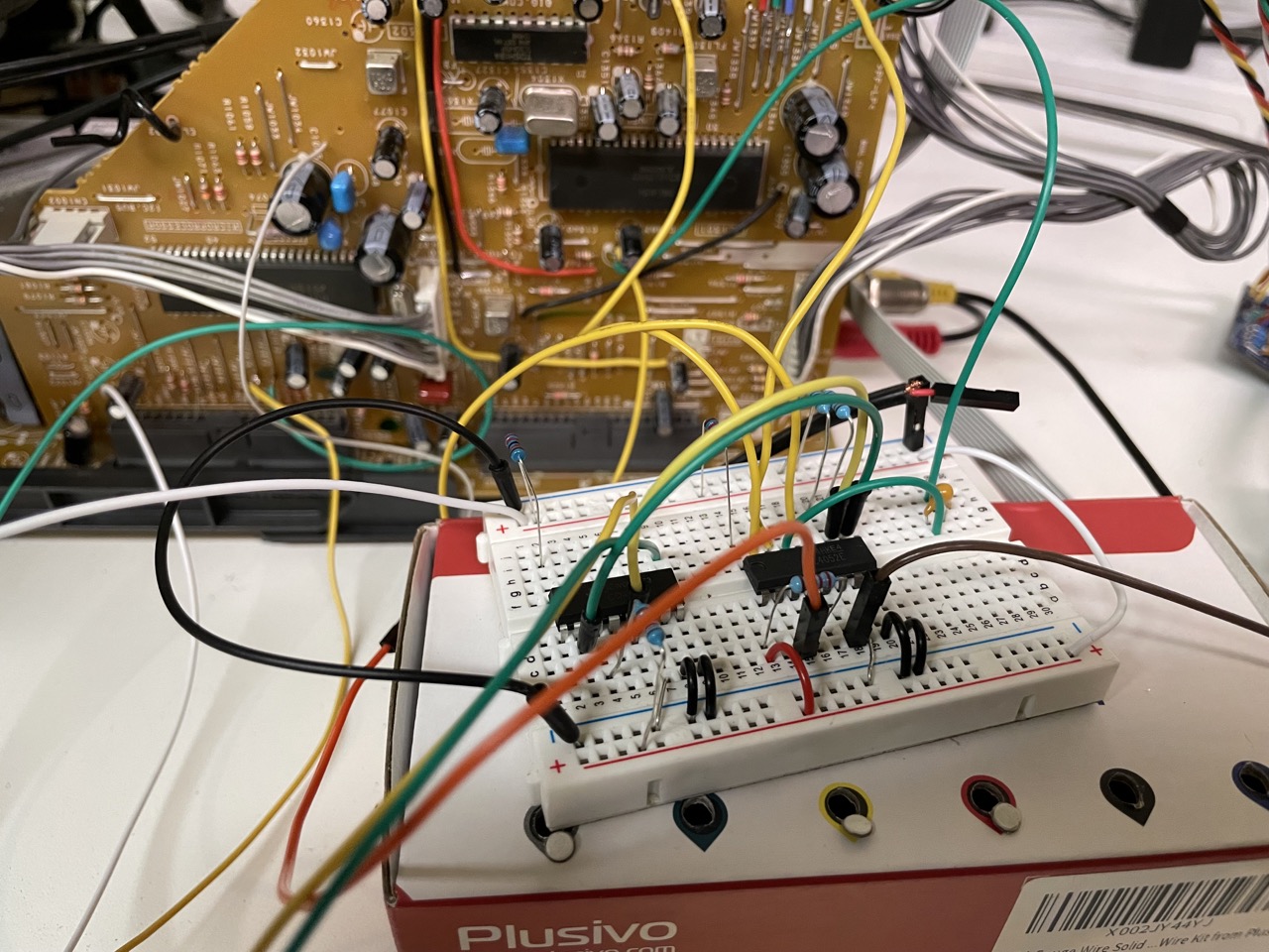
The following pictures show the circuit implemented on a breadboard and the final one:
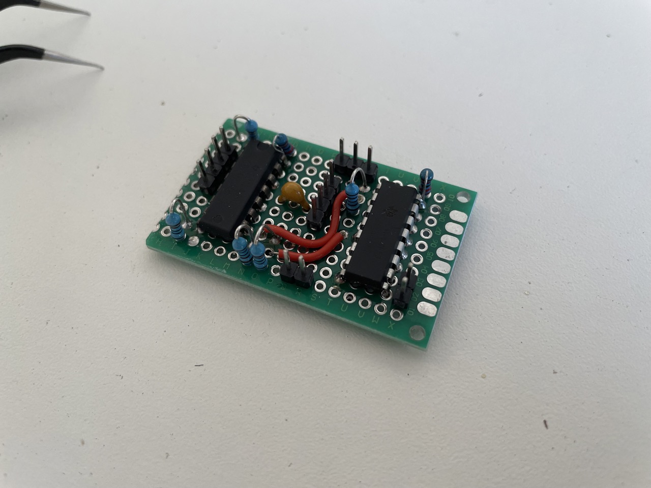
After adding all the mods the final board looks like this:
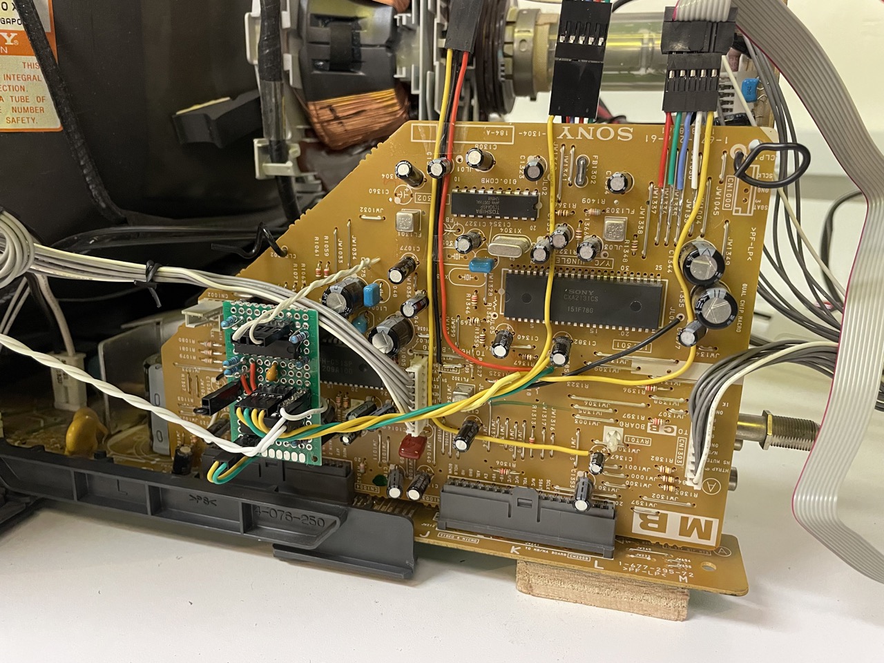
The push button is hidden behind the panel door. When it is On we have RF + RGB (Video1) + Component (Video2), and when it's Off we have RF + composite (Video1 and Video2) + S-video (Video1).
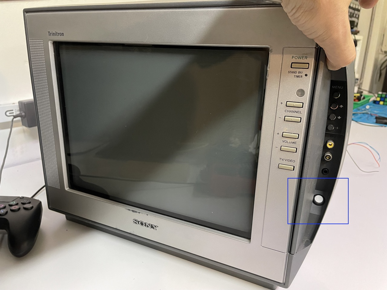
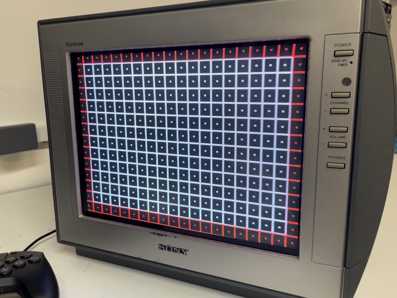
This little TV now has all possible input types, and the image is incredibly good, one of the sharpest I've seen on a consumer 13".
This was a nice project, again mostly driven by learning how to add all the missing inputs on a BA5 chassis.
Of course each one of the mods can be done independently if needed; I hope that people that are planning to mod a similar CRT will find it useful.
Let's conclude with a few pictures showing the TV and the image quality:



 This work is licensed under a