Summary
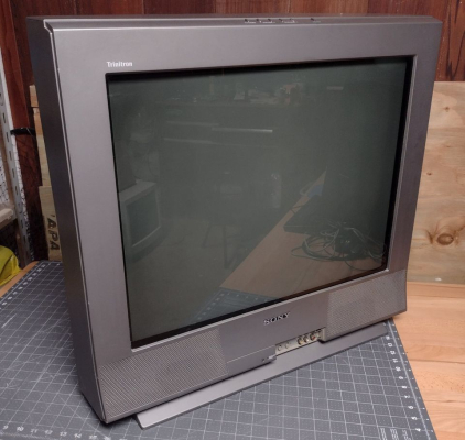
Mid-range 27" model from Sony's flat screen Wega line. Picture quality is very sharp, as the tube has a finer pitch than earlier curved Trinitrons of the same size and it includes component video inputs. However, due to the flat tube design these TVs often need adjustments to fix geometry and convergence problems that have developed over the years.
Literature
Notes
A common problem with Sony's flat CRTs is horizontal bowing, especially near the bottom edge of the screen. This is usually caused by poor yoke alignment, and can be corrected. For more information, see the "Adjusting a Flat CRT Yoke" page.
The BA-5D chassis can easily be modded for RGB through the OSD mux method. This can be beneficial, as these TVs have edge enhancement features that can cause ghosting and color separation. Adding RGB can result in a cleaner picture.
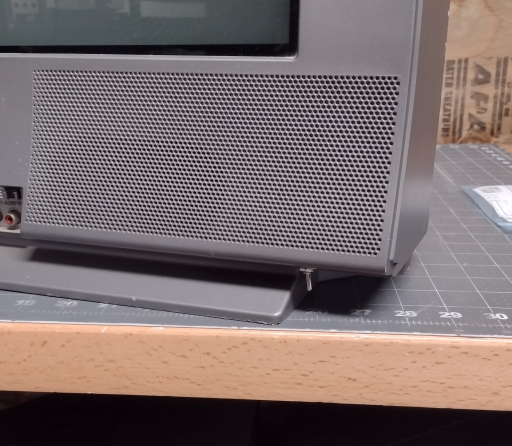
This was the last series of Sony's CRTs with bottom mounted speakers.
RGB Mod
Written by Matt Ross (6tanks)
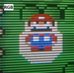
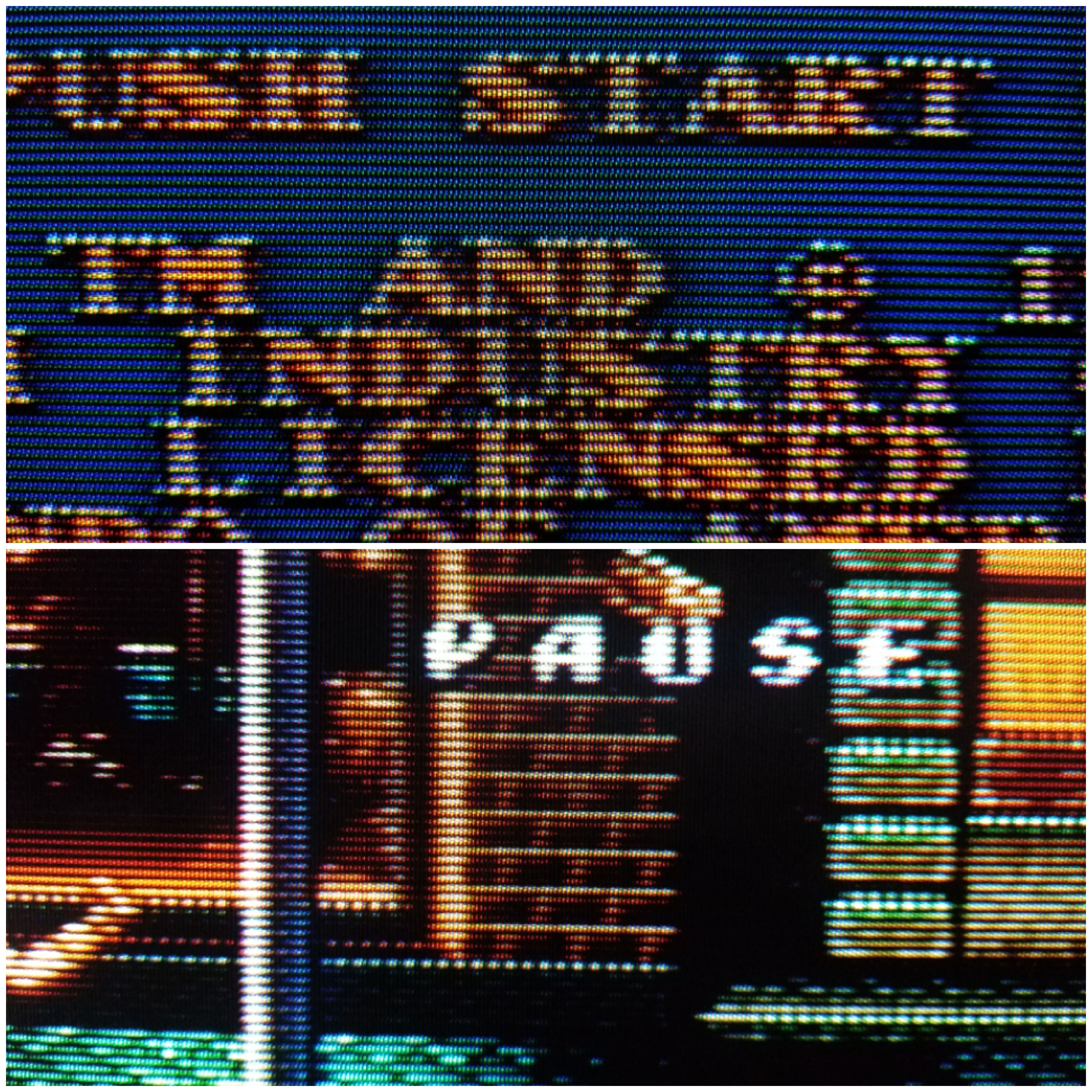
Like Sony's earlier BA-4 and BA-4D chassis design, the BA-5 can be modded for RGB via the on screen display (OSD) circuit. Although most of these TVs do have component video inputs, there are some flaws in the signal processing that can be bypassed with an RGB mod, resulting in slightly better image quality. This can be seen in the following two photos. In the first image (displayed through the component input), notice how one of Mario's eyes is bigger than the other and a slight ringing effect is visible on the edges of bright obects. This is due to artificial sharpening and misaligned chroma. In the second photo, edges are clean and both of Mario's eyes are the same size.

The TV pictured in this guide is a KV-27FS13, but it should apply to any 27 or 32 inch Wega with a BA-5 chassis. 13, 20, and 24" BA-5 Wegas use a different jungle chip and PCB design, so some details of the mod will be different.
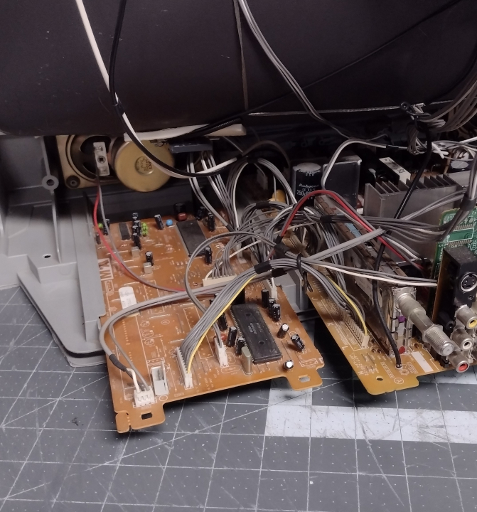
On these TVs, the microcontroller and jungle chip are both located on the MA board, located to the left of the main chassis. Aside from connecting the audio and sync, all the necessary work will be done on this section.
As can be seen in the service manual, each OSD signal passes through a voltage divider and a 0.01uF coupling capacitor on its way to the jungle chip.
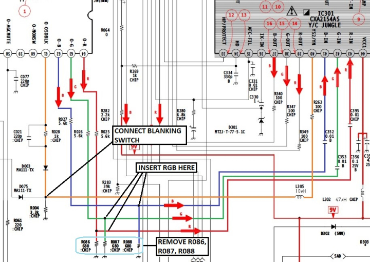
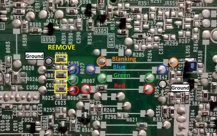
To insert our RGB signals, we need to remove the 3 resistors to ground (R086, R087, and R088), and connect the RGB signals before they pass through the 0.01uF capacitors. If using a SCART connector, wire it up as follows:
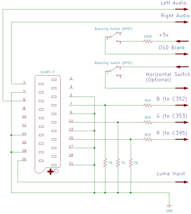
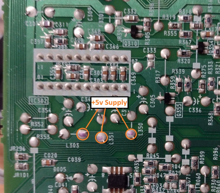
Each RGB line must have a 75 ohm terminating resistor to ground and, to maintain OSD function, an 820 ohm inline resistor before connecting to the chassis. Blanking should be connected to a +5v supply via a 1000 ohm resistor. Sync (ideally in the form of composite video or luma) is connected to the Luma pin of either the S-Video or Component Video input jacks.
The 3 resistors that need to be removed are all located near the top of the microcontroller, along with some potential attachment points for the RGB and blanking signals.
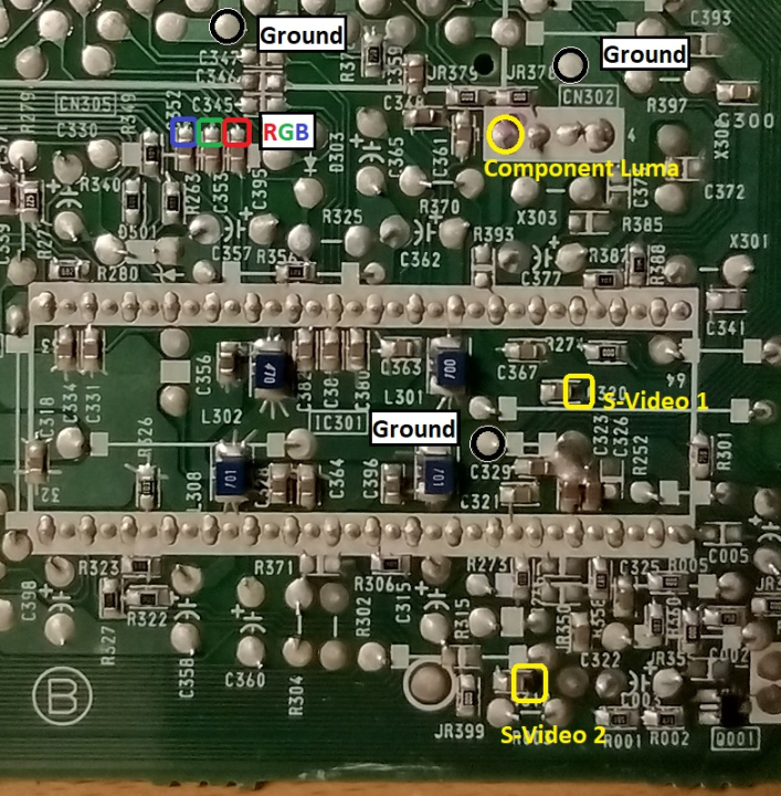
Alternative solder points for the RGB signals, as well as points to inject the sync signal, can be found near the jungle chip. Note that, normally, the S-Video 2 input is only available on the FV17 model.
+5v points for blanking can be found near IC302, the small chip at the corner of the board.
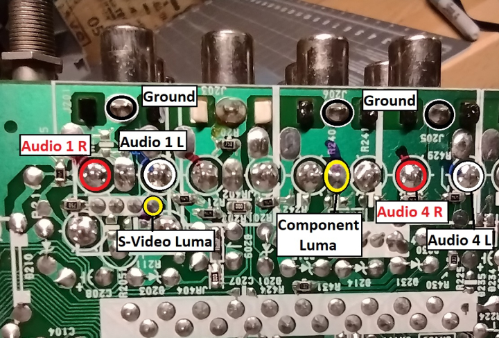
On the A board, Audio signals and sync can be routed to the bottom of the AV input connectors.
This example uses the Video 1 Luma input for sync, with everything connected using 16 gauge ribbon cable. RGB, sync, and video ground are connected to the MA board, with sound and audio ground on the A board. The wires are secured with a bead of hot glue and routed off the left hand side of the PCBs. It's a good idea to use quick connects so that the back case can be easily removed.
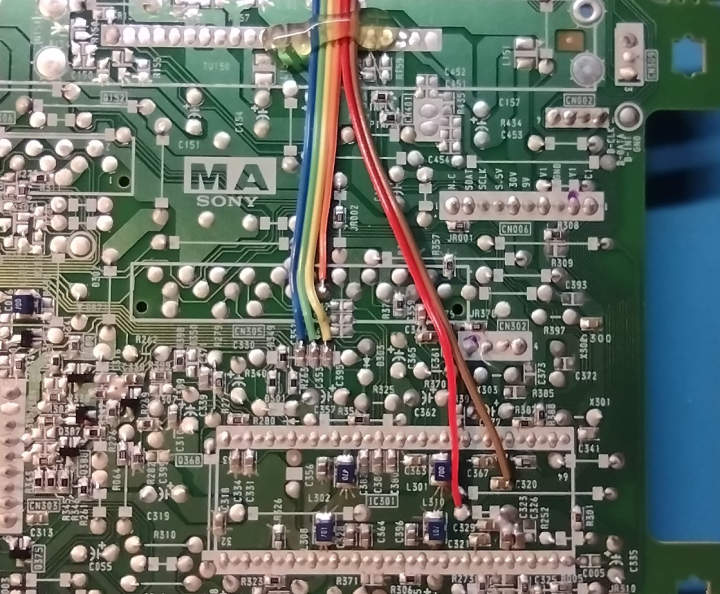
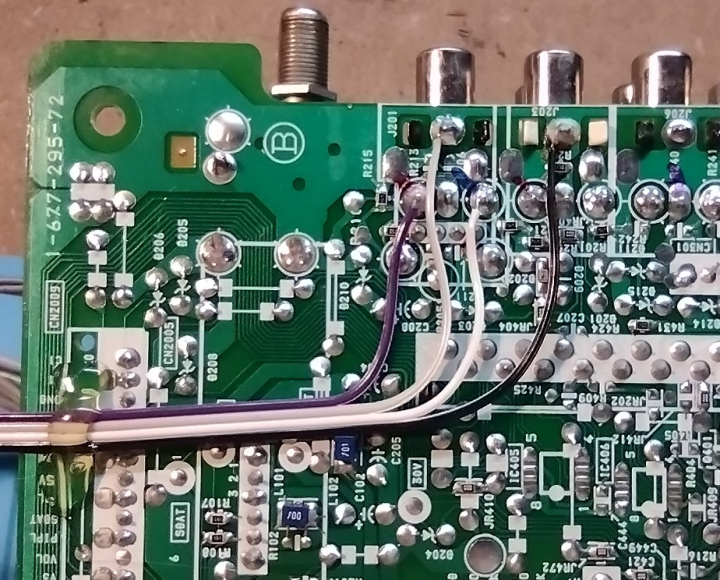
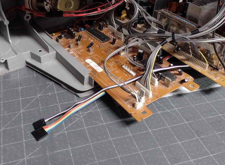
Blanking and +5v are routed to the front side of the PCB, and connected to the blanking switch via a quick connect. The 1000 ohm resistor is attached to one leg of the blanking switch.
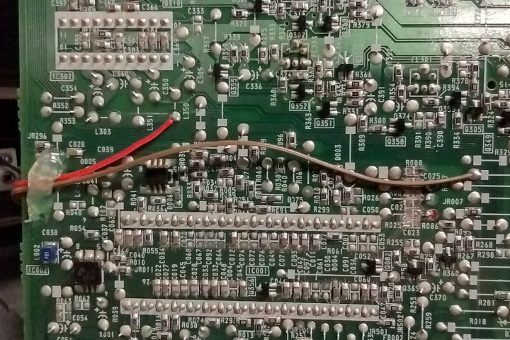
One useful feature of these TVs are two small white switches near the yoke connector: SW501 and SW502. These control horizontal position and can, optionally, be wired in tandem with the blanking switch to compensate for the horizontal shift in the picture when switching to RGB.
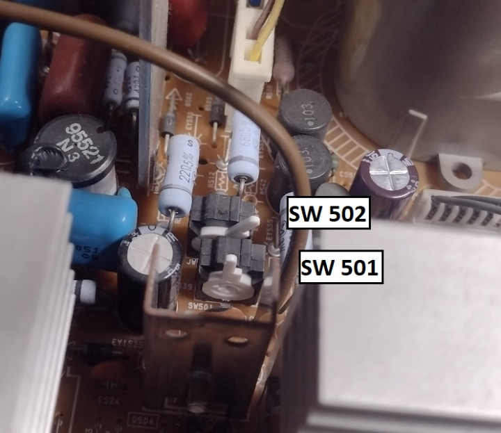
To use these switches, SW501 must be in the center position, and SW502 in the right position (as seen in the above photo). Now, connect two wires to the 2nd and 4th pins of SW 502 the bottom of the PCB. These should be wired so that the switch is open when blanking is enabled and closed when it is disabled (opposite to the other 3 poles). Heavier wire such as 24 or 22 gauge should be used.
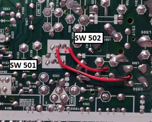
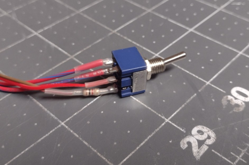
The position switch wires can be routed through small holes to the top of the board and connected to the blanking switch with a quick connect.
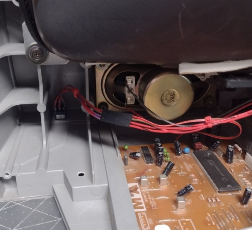
I found that the bottom right corner of the case was a convenient place to mount the switch, since it's close to the MA board and easy to access for the user.
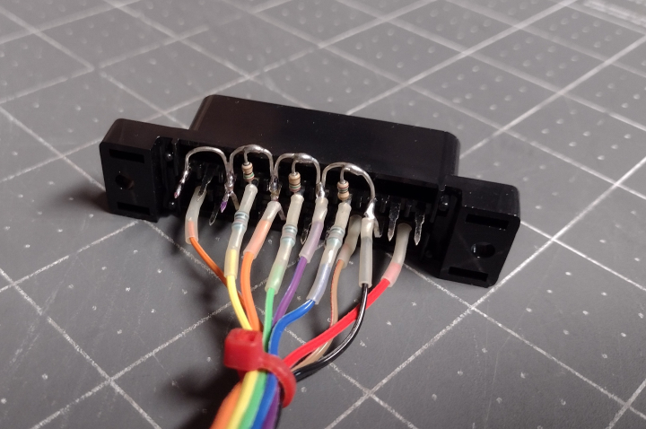
The SCART connector is wired up with all ground pins connected together, 75 ohm terminating resistors installed, and 820 ohm mux resistors inline with the RGB leads. For more information, visit the SCART installation guide.
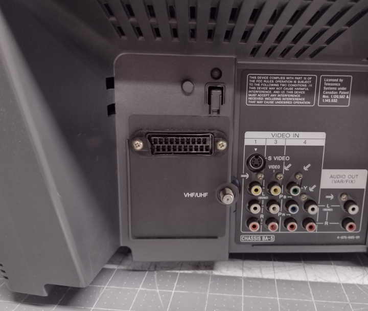
The SCART connector can be neatly mounted in the space above the tuner. On higher end models with a second tuner, however, it may be necessary to find a different location.
Now that the mod is done, the TV will display a clean RGB image when the blanking switch is enabled and the TV is set to the correct A/V input. The picture will be shifted horizontally somewhat. To compensate for this, refer to the service manual and adjust HPOS so that the image is centered. If the horizontal position switch has been connected properly, the picture should remain centered in both RGB and A/V modes, otherwise it will have to be manually adjusted when changing input types.
Composite 240p Performance
by Eli Krause
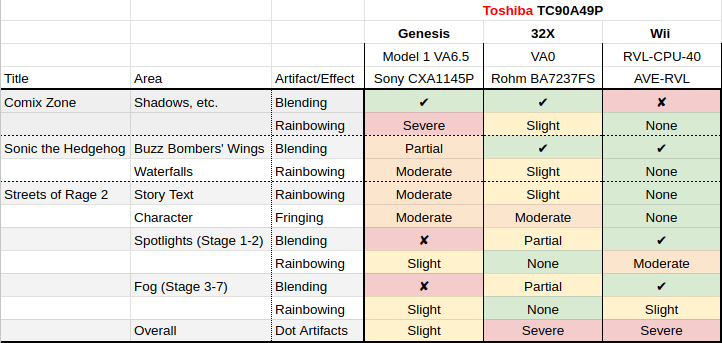
For composite decoding this set uses a Toshiba TC90A49P, a 3-line digital comb filter. Depending on the console/revision, dot artifacting ranges from slight to severe, and blending effects may be broken. If the set has an s-video or component YPbPr input, then using a good external notch filter to decode composite instead and sending that to the set would blend all dithering patterns and avoid nearly all dot artifacts (full guide here).
Gallery


 This work is licensed under a