Panasonic CT-13R17B
November 27, 2024, 2:41 am
January 19, 2025, 12:54 am
Summary
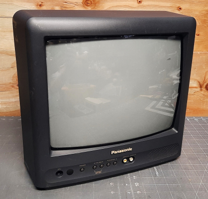
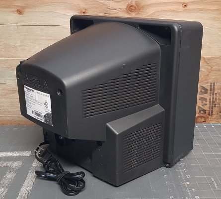
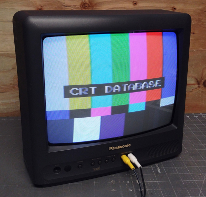
13" consumer TV, manufactured by Orion and sold by Panasonic. It has a single front mounted composite input and a mono speaker. Picture quality is quite good, as the tube is finer pitch than some other Orion TVs of the same size. It can be modded for RGB input.
Manuals
Notes
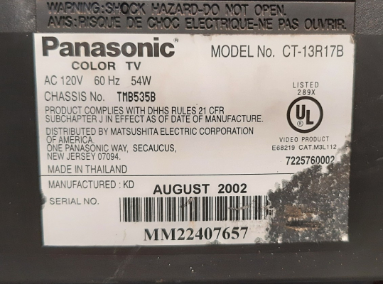
Two other models of this TV were produced; one with a silver shell (CT-13R37S) and one with a white shell (CT-13R27W). They use the same chassis as the Toshiba 13A22. Service menu operation is identical as the Toshiba A/AF series and other Orion-built TVs.
Later models of this TV, such as the Panasonic CT-13R38B and Toshiba 13A23, use a 1-chip chassis design and cannot be RGB modded.
Like other Orion TVs, this model lacks an input select button on the front panel. However, the AV input can be selected using the channel up/down keys. Aside from the service menu, all of its functions can be accessed without a remote.
RGB Mod
Written by Matt Ross (6tanks)
TVs with the Orion TMB 535 chassis can be modified to accept RGB via the OSD circuit. The TV pictured in this guide is a Panasonic CT-13R37S, but it should also apply to the Panasonic CT-13R17B & CT-13R27W, as well as the Toshiba 13A22.
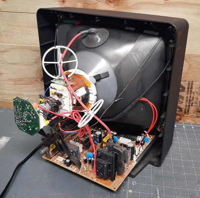
The jungle chip is a Mutsibishi/Renesas M61250FP, which has been configured for analog input. It is located near the front of the TV near the A/V jacks, and most of the work will be done in this section.
As can be seen in the service manual, each OSD signal passes through a set of voltage dividing resistors and a 0.1uF coupling capacitor on its way to the jungle chip.
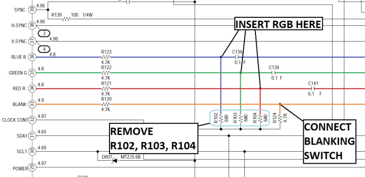
To insert our RGB signals, we need to remove the 3 resistors to ground (R102, R103, and R104), and connect the RGB signals before they pass through the 0.1uF capacitors. If using a SCART connector, wire it up as follows:
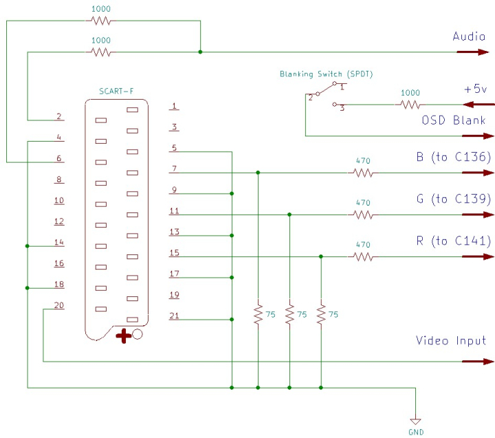
Each RGB line must have a 75 ohm terminating resistor to ground and, to maintain OSD function, a 470 ohm inline resistor before connecting to the chassis. Blanking should be connected to a +5v supply via a 1000 ohm resistor. Sync (ideally in the form of composite video or luma) is connected to the front video jack. Left and right audio are mixed using 1000 ohm resistors and routed to the front audio jack.
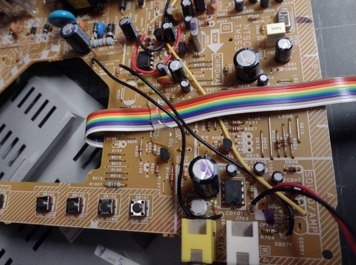
The 3 resistors that need to be removed are all located near the microcontroller chip:
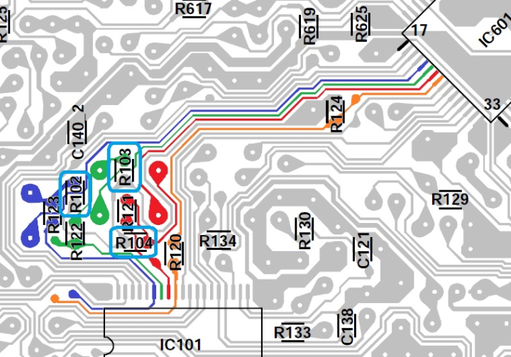
This area provides all the necessary connections for the mod. Red, Green, and Blue signals can be soldered to the bottom of the coupling capacitors. There is a small solder pad for blanking near the jungle chip, and +5v can be taken from the voltage regulator Q604. Sync and audio can be attached to the bottom of the front A/V jacks.
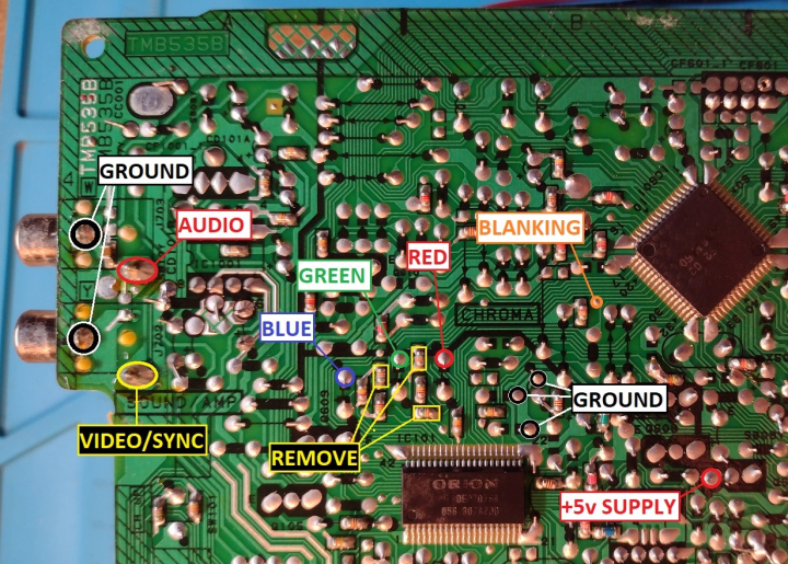
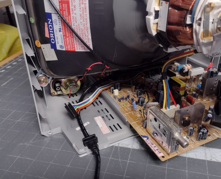
I used 26 gauge ribbon cable for wiring. With everything soldered in place, the wiring can be run through the large hole to the top of the PCB, routed to the left side of the board, and secured with beads of hot glue. It's a good idea to use a quick connect so that the back case can be easily removed:

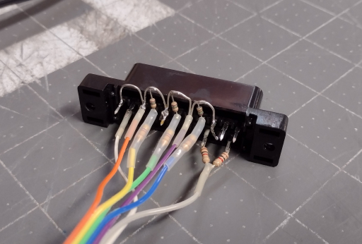
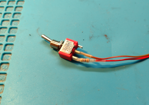
The SCART connector is wired up with all ground pins connected together, 75 ohm terminating resistors installed, and mux resistors in line with the RGB leads. For more information, visit the SCART installation guide. The 1000 ohm resistor is attached to one pole of the blanking switch.
The SCART socket can be mounted vertically, to the left of the RF tuner. This gives it plenty of space and keeps the wiring away from the power supply, which can cause interference. The rear of case near the bezel provides a good spot for the blanking switch.
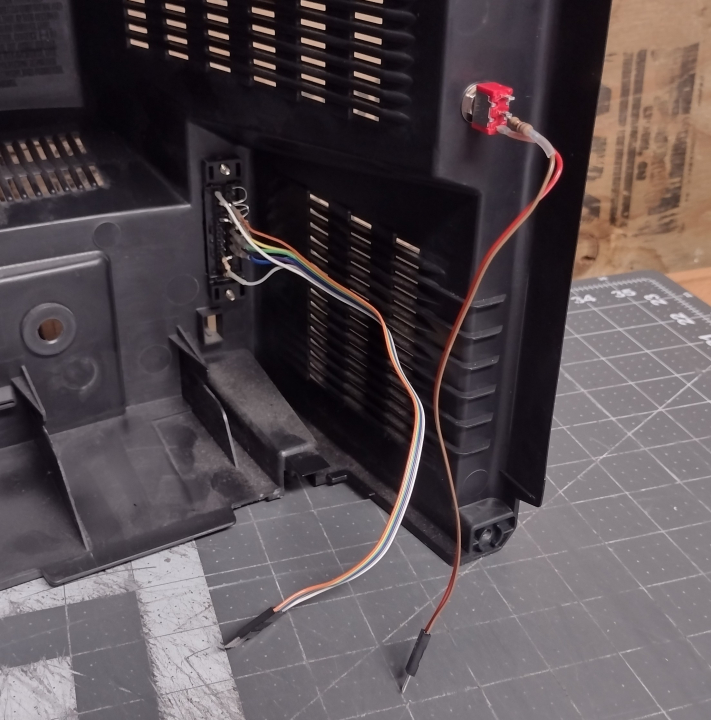

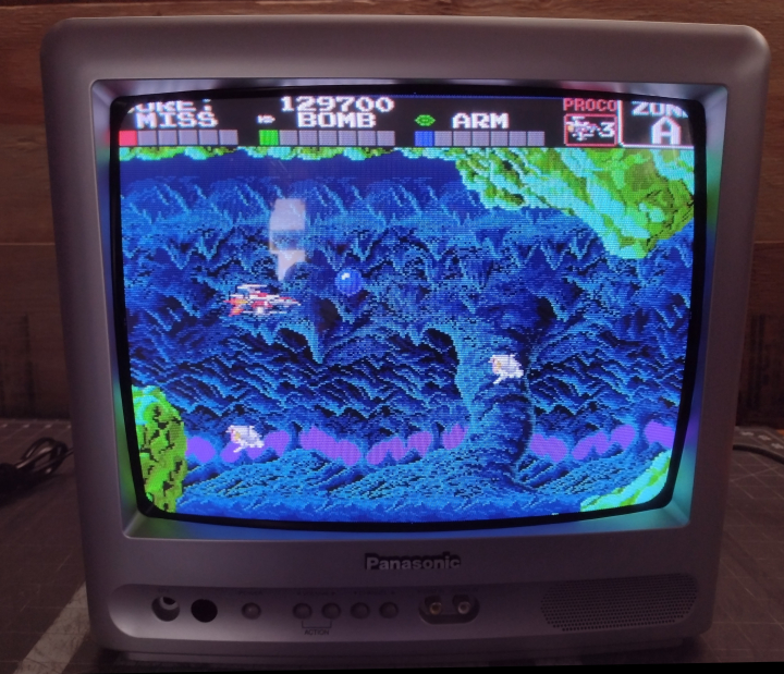
Now that the mod is done, the TV will display a clean RGB image when the blanking switch is enabled and the TV is set to A/V input. The picture will be shifted horizontally somewhat. To compensate for this, refer to the service manual and adjust H Phase so that the image is centered.
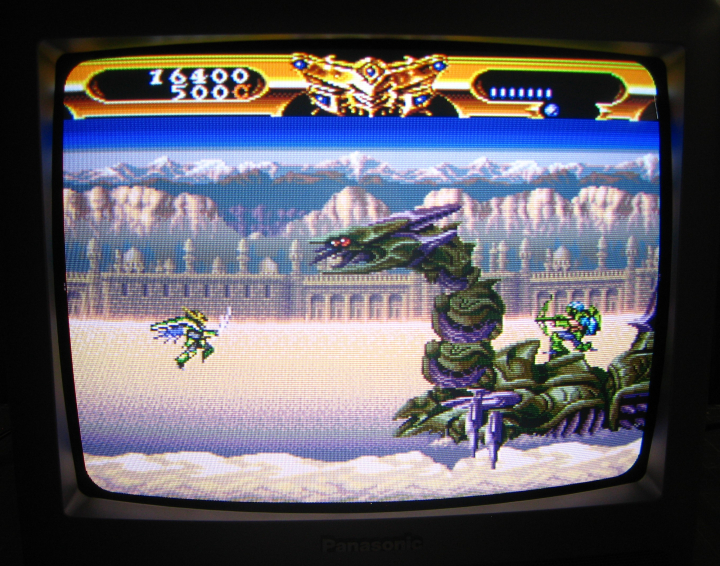
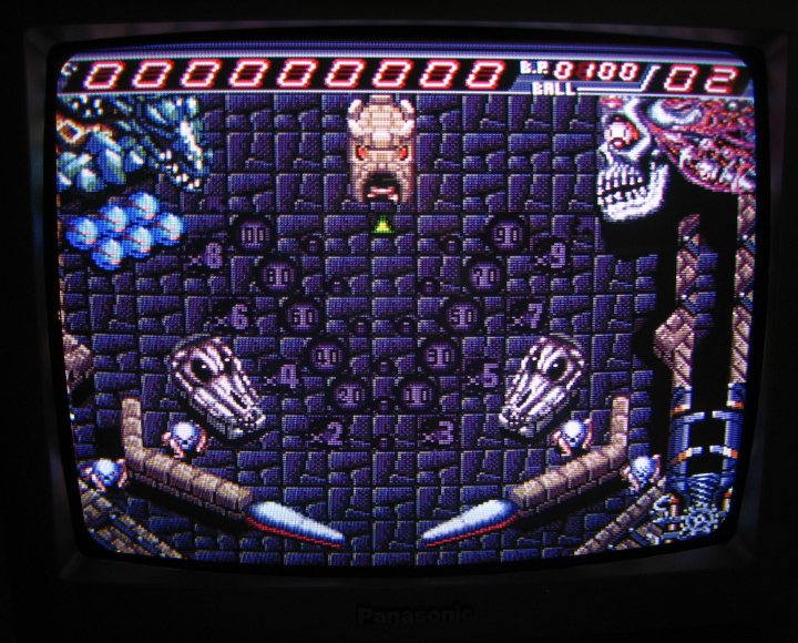
Gallery
| Specifications | |
|---|---|
| Brand: | Panasonic |
| Manufacturer: | Orion |
| Model: | CT-13R17B |
| Series: | CT |
| Viewable Size: | 13" |
| Input Signals: | Composite, RF |
| Native Resolutions: | 240p, 480i |
| Horizontal Scan Range: | 15 kHz |
| Vertical Scan Range: | 60 Hz |
| Formats: | NTSC |
| Aspect: | 4:3 |
| Adjustments: | OSD Customer Controls, OSD Service Menu |
| Horz. Output Transistor: | 2SD2499 |
| Vertical Output IC: | AN5522 |
| Jungle IC: | M61250FP |
| Comb Filtering: | None |
| Flyback: | FQI-14B001, FQI-14B005 |
| Tube: | Orion , A34AGT13X98 , A34AGT13X , A34JXV70X53 , A34JXV70X |
| Heater Voltage: | 6.3v |
| Deflection: | 90° |
| Mask: |
Slot

|
| Tint: | Dark |
| Removable Glare Film: | No |
| Yoke: | CDY-FM1401A |
| Yoke Horz. Inductance: | 4.102 mH (@ 10 kHz) |
| Yoke Vert. Inductance: | 29.46 mH (@ 100 Hz) |
| Yoke Horz. Resistance: | 6.29 ohm |
| Yoke Vert. Resistance: | 15.71 ohm |
| Speakers: | Mono |
| Remote: | EUR501450 |
| Chassis: | TMB535 |
| Weight: | 21 lbs (9.5 kg) |
| Dimensions (W/H/D): |
359 x 337 x 354 mm
(14.1 x 13.2 x 13.9") |
| Application: | Consumer |
| Cabinet Material: | Plastic |
| Launched: | 2002 |
| Country of Manufacture: | Thailand |
| Mods: | RGB via Mux |
| Degaussing: | Automatic on Power-on |
 This work is licensed under a