
Summary
250 TVL version of the 8044Q. Difference between 8041Q and 8042Q is front panel toggle controls. 41Q has underscan 16:9 toggle on the back, 42Q moved the control to the front and added a manual degausser button. Known as the 9041Q outside of the US.
Literature
Optional Accessories
- Battery: NB-1B
- Charger unit: BC.1WD
- Rack kit (5 rack units high): MB-507
- Blank panel: MB-509
Notes
The A20JMP10X tube inside is directly interchangeable with the higher TVL M20JMP10X tubes of the 8044Q, 8045Q, and 9L3 PVMs and will result in a dramatic increase in scanline definition and detail. Inversely, if you replace an M20JMP10X with the A20JKU10X, the TVL will decrease dramatically and you will completely lose scanline definition.
Common Problems
The anode cap in most Sony 8" and 5" PVMs are sealed to the tube with grey or white silicone. This silicone can be removed by soaking it with ethanol. Do not try to cut around the silicone, you will likely destroy the rubber cap. The HV is relatively low in these CRTs compared to a normal CRT so you may be ok to use a damaged rubber cap, but please try to remove it properly first before resorting to brute force.
The 8" and smaller Q series monitors have several common problems:
- Brittle plastic inside chassis - due to bad plastic formula and heat exposure over time, many of the higher-hour 8" PVMs will have extremely brittle plastic inside the chassis. This includes the PCB trays and the H-Center potentiometer on the P board (under the tube).
- Won't power on from AC - the modular SMPS power supply is a common failure point - if your 8" PVM won't power on then take the power supply out and replace all of the electrolytic caps inside. There are not very many. If problem persists then try powering the PVM using the DC input on the back - if it works while using DC power then you still have a dead SMPS or there is a problem in the small area of the D board that handles the incoming 40v from the SMPS before starting up the monitor. NOTE: If you are trying to power the monitor's 12v DC jack via clip leads and a bench supply, there is a push-pin latch that prevents the DC jack from drawing any power. You need to either push the pin in yourself, or wedge something into the switch latch on the back bottom side of the input board where the DC power jack is. I suggest wedging some foam or something into the front of the plug over the push-pin. If your power connection does not push this pin in, the monitor WILL NOT START from any provided 12v supply. Also note the monitor needs a large amount of amperage (~4 amps) in a brief startup surge. After startup it draws less than 1 amp. Make sure your power supply can provide at least 4 amps.
- Won't power on from DC 12v - The D board handles boosting the 12v to 40v - likely your D board just needs fresh caps. Start by replacing all the largest ones plus the ones near heatsinks.
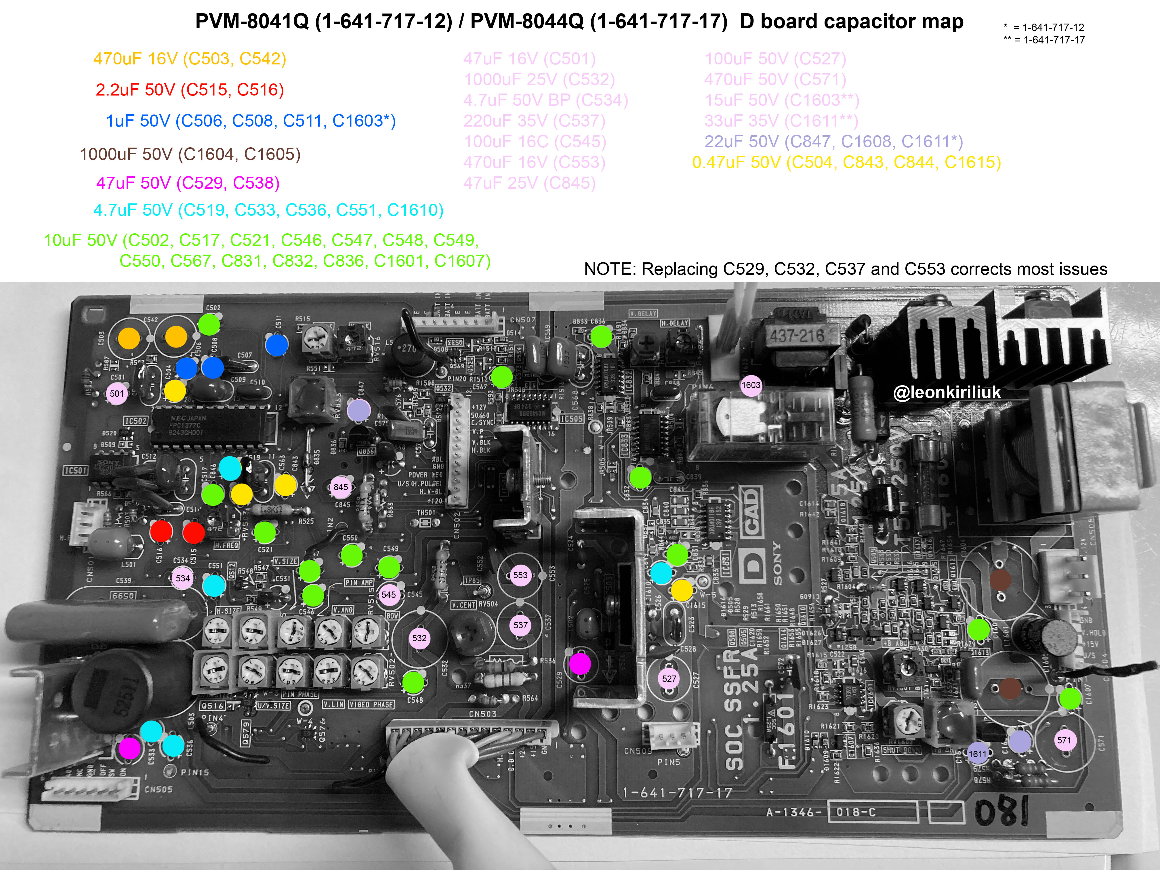
- Squiggly lines in grid test patterns or other deflection issues - replace C529, C532, C537, and C553.
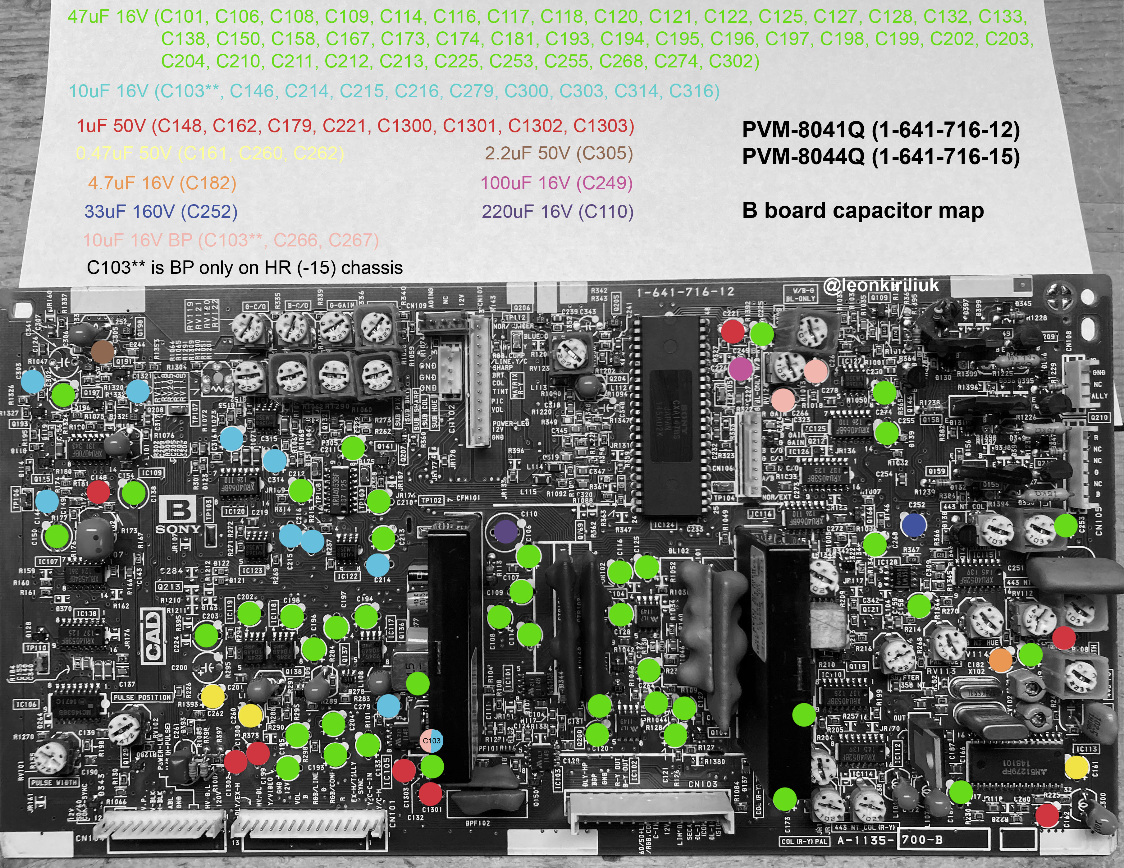
- Abnormally low brightness for one or more colors - recap the B board electrolytics. If you have more than one 8" PVM you can rule out the tube first by swapping out the B board for a known good one. If the problem still remains then you have a bad tube. If the problem goes away it's a bad B board.
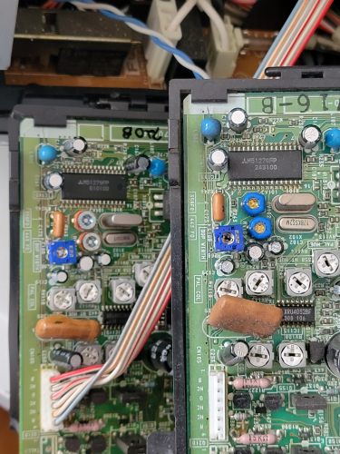
- Composite/S-Video is black and white - The B board has orange trimmer pots CV101 and CV102 for NTSC and PAL that eventually go bad (see image below). If your model has the orange trimmer pots they must be replaced. If your model has blue trimmer pots then they were already replaced by Sony and do not need to be replaced again. The part to order is a ceramic 100v trimmer capacitor with a range between 3pF to 10pF. You will also need to solder a 5pF 50v film capacitor across the legs of the trimmer pot. You may need to adjust the pots to get color to show. If replacing the trimmer pots doesn't bring color back, spray all pots on the B board with deoxit and give them a few spins (remember to take note of their original position). Try adjusting the "358FO" pot (its in the corner of the B board closest to the front of the tube). Reflow the solder joints for IC124 and all of the connectors for ribbon cables on the B board. If those don't fix the problem then recap B board.
- All inputs are black and white including RGB - reflow solder for the cable connectors on the CA board and B board. If problem persists then follow steps in previous bullet point.
- Arcing/pop noises during operation - remove anode cap (remember to follow proper safety precautions) and clean the anode area and rubber cap. Apply fresh Dielectric Grease to area.
- Broken H-center potentiometer - try centering your raster using the Video Phase pot (RV502) - if its too off-center for that to work (or if your H-centering glitches when you whack the side of your PVM) then you need to remove the broken H-center pot and replace it with two 2w 50-60ohm resistors. Each resistor should connect from the common side of the potentiometer to the respective output, forming a V-shape. See here for images.
- Burn-in on picture tube or picture tube needs replacement - all of the 8" PVM tubes are interchangeable and there are two additional oscilloscope tube models which will work - M20JMP11X and M20JMP16X. The 11X uses the same Yoke as the 10X so you don't need to swap them, but the 16X uses a different yoke which will have to be replaced with the one off your original tube. You can upgrade your A20 tube to the M20 tube for a serious improvement in vertical resolution and overall picture quality - you will have visible scanline gaps on an 8" tube!
- Degausser doesn't seem to really work - these PVMs only have a partial degaussing coil wrap - the coil is on the top edges of the tube but not the sides. This means you won't see all the crazy color distortion you are used to when you use a PVM degaussing button. You also won't hear any BONG noise, just the click of a relay. Rest assured that as long as you see the raster size increase during the degauss, your coil is working.
Capacitor Map
NTSC / PAL Trimmer Caps
Gallery


| Specifications | |
|---|---|
| Brand: | Sony |
| Manufacturer: | Sony |
| Model: | 8041Q, 9041Q |
| Series: | PVM Q-Series |
| Viewable Size: | 8" |
| Input Signals: | Composite, S-Video, Component YPbPr, RGB |
| Sync: | CSYNC, Sync on Green, Sync over Composite, Sync on Luma |
| Native Resolutions: | 240p, 480i |
| Linecount: | 250 TVL |
| Formats: | NTSC, PAL, NTSC4.43, SECAM |
| Aspect: | 4:3 |
| Adjustments: | Internal Potentiometers, External Potentiometers |
| Tube: | Sony Trinitron , M20JMP10X , A20JKU10X |
| Deflection: | 70° |
| Mask: |
Aperture Grille

|
| Pitch: | 0.5 mm |
| Tint: | Dark |
| Speakers: | Mono |
| Chassis: | SCC-E96A-A |
| Weight: | 17 lbs (7.7 kg) |
| Application: | Professional |
| Cabinet Material: | Metal |
| Country of Manufacture: | Japan |
| Market: | North America |
| Power Standard: | 120v |
| Mounting: | Rackable |
| Degaussing: | Automatic on Power-on, Manual |
| Tag: | Needs Measurements, Needs Yoke Info |