
Table of Contents
What is a CRT Tester?
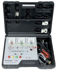
CRT Testers (or as the industry used to call them, CRT Analyzers) are tools designed to emulate some of the conditions necessary to drive a cathode-ray tube (CRT) so that its operation and condition can be analyzed and evaluated. They can identify (and in many cases resolve) common issues that develop in CRTs such as G1 shorts, as well as measure the strength left in the cathodes of the electron guns - thereby giving an accurate estimate of wear on the tube.
Different testers have different ranges of settings / capabilities, but the general list includes the following:
- Tube Socket Adapters
- Filament voltage
- G1 bias
- Cutoff (G2 for each color) with current meter (Note: some testers can only test one color at a time, some can test all 3 at once)
- G1 / H-K Shorts Testing
- Life Test
- Restoration (a.k.a. Rejuvenation, Clean & Balance, Re-Activation, etc)
General Overview, Approach, and Theory
In this section I will cover all of the above-listed features in detail, and provide insight into the importance of each one as well as any tips I've learned over the years.
Tube Socket Adapters
There were many different tube socket sizes and pin counts used through the decades, and no single tester's set of adapters will be guaranteed compatible with everything. Sencore had a pretty ingenious set of double-sided adapters that covered a wide range of socket sizes using only 5 physical adapter pieces, but even that system has its compatibility limitations. When choosing a CRT Tester you want to make sure it comes with as many adapters as possible - you should research what the most common tube sockets you work with are so you can be sure to get those adapters. Most adapters cannot be found separately anymore and only come bundled with testers. Your only option for sourcing new adapters is to make your own. Specific instructions for making your own adapters, if we have them, can be found on the respective page for your CRT Tester.
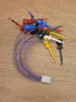
When you inevitably run into a tube socket that you don't have an adapter for, you will need something called a Universal Adapter - similarly to the socket adapters you can make your own if you don't have one. The universal adapter is a set of clip leads that allow you to manually attach the tester to the pins of the CRT. Care must be taken to hook these up properly to prevent damage to the CRT and its physical pins.
Filament (a.k.a. Heater) Voltage
This is the voltage that heats up the filament in the neck of the CRT. You can think of this exactly the same as an incandescent lightbulb. The filament wire in a CRT neck is rated for a specific voltage (generally 6.3v) and is capable of being driven higher than spec for rejuvenation purposes, but eventually has a breaking point where the filament will permanently burn out similarly to an overloaded fuse. A CRT with a burned out filament is not recoverable and must be discarded, just like a broken lightbulb.
Generally a tester's filament voltage setting will be a selectable range from 0-14v or have presets for common voltages. Most CRTs use the standard 6.3v but there are several common tubes that use non-standard values (such as Sony's 8" A20JKU10X with a 4.5v filament) - so having a tester with a selectable filament range is important. The value you choose here must match the value the tube normally operates at for an accurate emissions test result. You can find this information in CRT set-up charts, or by checking the schematic/service manual of the TV, or (as a last resort) by measuring the filament pins on the neckboard with a multimeter in AC mode while the CRT is powered.
G1 Bias
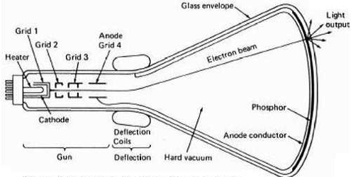
CRTs have multiple "grids" in their neck structure, just like a traditional vacuum tube. "G1" refers to "Grid 1" which is the control grid. Think of G1 like an adjustable aperture lens that the electrons must pass through to reach the front of the CRT - the higher the voltage is, the smaller the aperture is. The polarity of G1 voltage is negative (so for example a high G1 voltage would be -180v), but certain testers may or may not make this distinction in their knob labels. The higher G1 your tester is capable of going, the more accurately you can test high TVL tubes like PC monitors or high end broadcast tubes. If your tester is not capable of matching the operational G1 voltage of a given tube, the emissions test results will not be accurate. Many older testers are not capable of a G1 voltage high enough for modern tube testing.
You can check G1 bias using the tube charts from the brand of your tester - Sencore and BK have the most comprehensive tube charts.
G1 / H-K Shorts Testing
Often times a short circuit can develop between the control grid (or filament) and one or more of the color cathodes in the CRT neck. It is speculated that this can be due to either manufacturing defects (debris was airborne during the vacuum seal of the tube and was trapped inside) or due to tungsten burnoff from the filament over time. Regardless of the cause, this short circuit can cause many issues to appear in a CRT such as:
- Flickering/Intermittent color haze over the entire screen - the color of the haze depends on which color cathode(s) are shorted to the G1 grid or Heater.
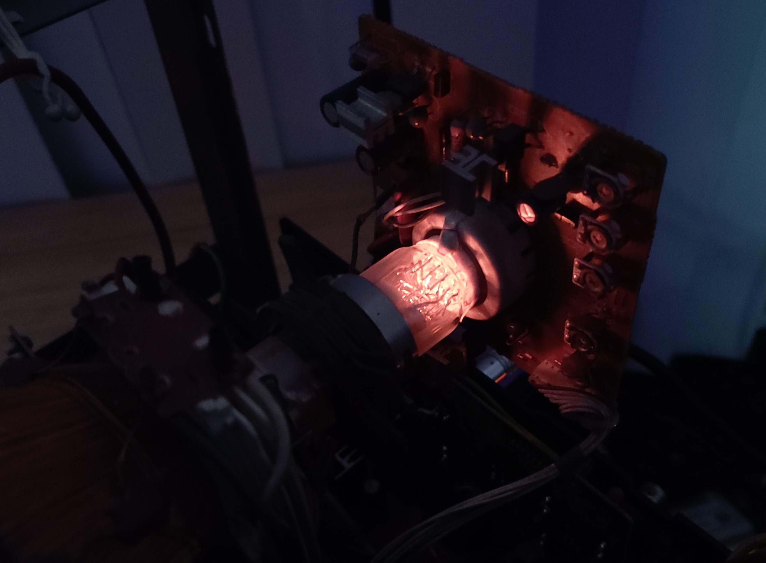
- Visible arcing or audible popping coming from the neck of the CRT (see animation on right)
- Very dark color(s)
- Extreme black crush (a good test for this is the Color Bars pattern in 240p Test Suite)
Most CRT Testers can tell you immediately if a CRT has either a G1 short or an H-K short. G1 shorts can be fixed if the tester has a "shorts clear" function, but testers cannot fix H-K shorts. There is an old-school method for fixing H-K shorts that involves isolating the heater voltage from chassis ground by winding your own transformer off the flyback. You can read more about that here.
Cutoff (G2)
Cutoff refers to a CRT's ability to achieve proper black-levels. Every tester has specific instructions for how to calibrate Cutoff and you will need to refer to the manual for the steps to follow. If after following those steps you still cannot calibrate for a proper cutoff baseline then the tube is likely extremely worn.
Confusingly, most testers refer to G2 for cutoff even though cutoff is manipulated by both G2 and G1 voltage. You can think of the triode section of the electron gun (cathode, G1, G2) as a valve. When drawing high luminosity colors, the valve is more open than when drawing low luminosity colors. How open the valve is determines the diameter of a circular region on the cathode that is actively emitting electrons into the cathode ray. There is a center region of the cathodes that emits for both dark colors and for bright colors. So the cathodes wear out faster in this region. The cutoff tests measure emissions with the valve almost completely closed, but not 100% closed. If emissions are too low, it indicates the cathodes are too worn out to achieve proper black levels. You will only be able to get a picture that has grey blacks (too bright) or has black crush (too dark).
Cutoff test failure could also indicate a possible G1 short in the tube. Finally in some rare cases the CRT could require a cutoff voltage that is higher than the tester is capable of providing - in these cases you will not be able to accurately test the tube cutoff or emissions. In this scenario you won't be able to make the cutoff dials move at all, even in the highest supported G2 modes of your tester. This would be similar behavior to a tube that is extremely worn out - so you should try to verify the tube's required G2 voltage in the Ultimate Sencore Spreadsheet is supported by your tester before assuming any conclusions.
Focus (G3)
Some testers have the ability to test the Focus grid (G3) for proper operation and isolation. A CRT which fails the focus test will likely not have the ability to be focused using the flyback adjustment. Although I have been told that rejuvenation can resolve focus test failures, I have never personally ran across a tube that failed the focus test.
Emissions
The emissions test is the final step of testing a CRT - it will tell you how worn out the CRT is and whether a rejuvenation should be attempted. For those of you wishing that CRTs had hour counters - this is as close to that as it gets. Emissions tests evaluate the the cathode for the higher ranges of cathode current, which corresponds to the higher luminosity colors it can display (near-peak levels instead of near-black levels tested in the Cutoff step of testing).
Emissions tests can only be performed properly once all of the prerequisites of a "workable tube" are met:
- The tube has correct heater voltage and the heater light has been visibly checked by the test operator (if this step fails you either wired up the tube wrong or the heater is blown). Some heaters are pretty dim, you might have to turn off your lights to see it.
- No short-circuit indicator lights are lit on the tester (if they are, you need to resolve these before emissions can be tested)
- G1 bias of the tester is within spec of the tube (if not within spec, emissions readings will be artificially high)
- Cutoff calibration was possible and is within spec (if this step fails you already know the tube is worn out or has major issues)
- Your tester is capable of matching (or at least getting close to) the operating G2 voltage of the tube being tested. For most solid-state CRTs this is less than 600v but some older delta-gun style tubes can require G2 voltages as high as 700v+ for accurate emissions results. For some tubes this information can be found in the Ultimate Sencore Spreadsheet, or you can find it by looking at the schematic of the chassis (or tube, if available).
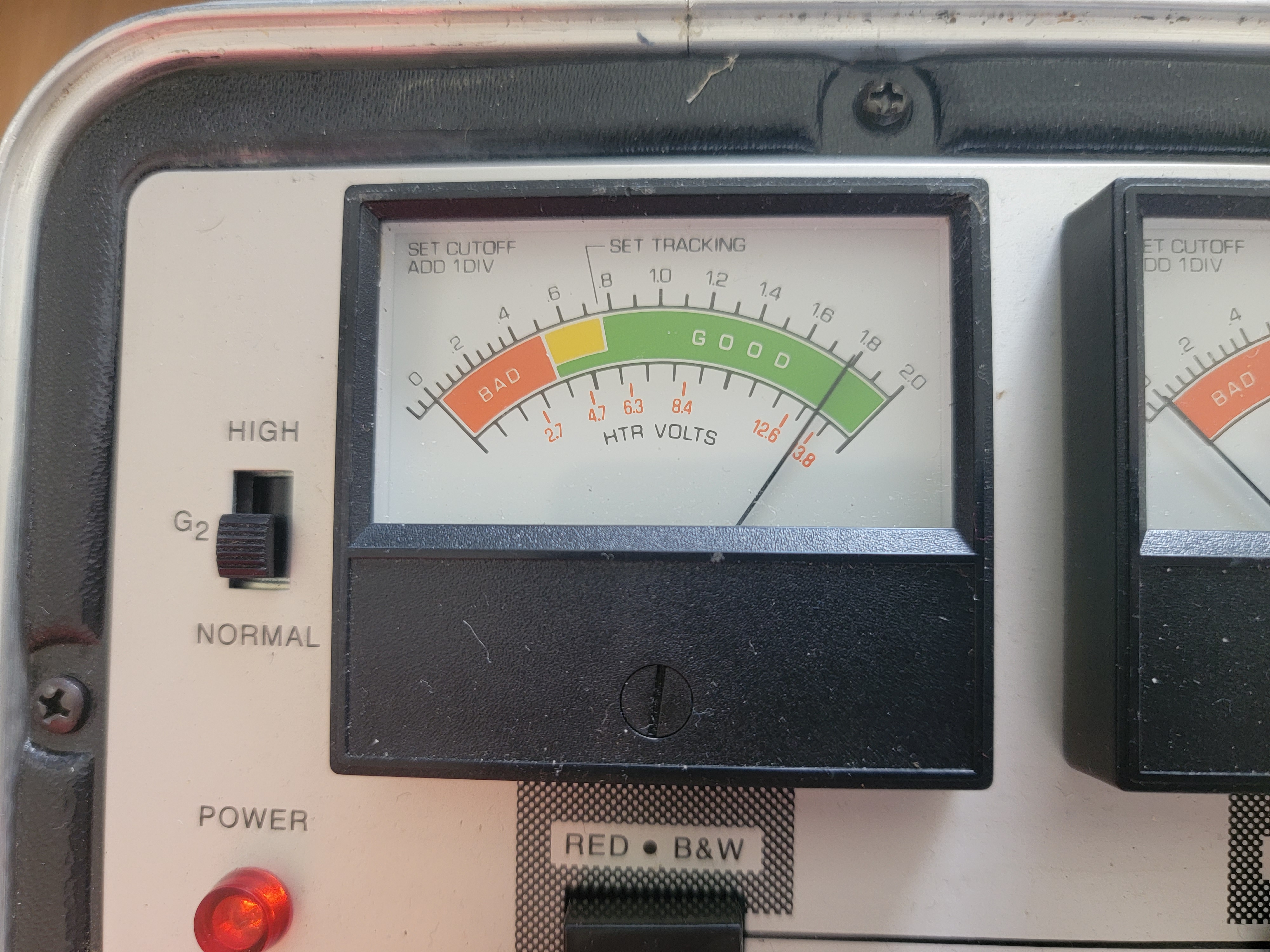
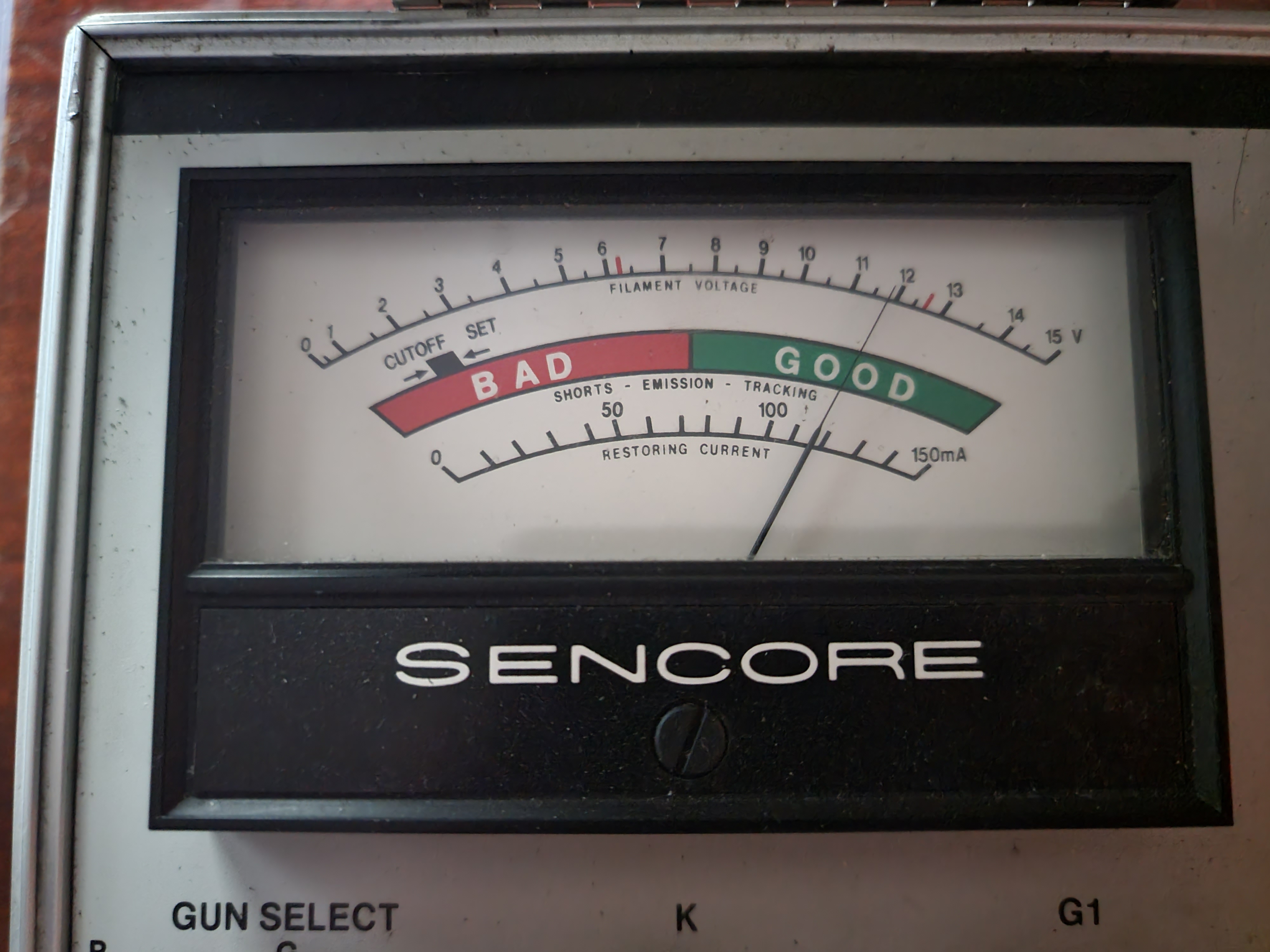
Once all of the above prerequisites have been met, you can get an accurate emissions test result from your tube. Most testers' emissions displays have a "good" (green), "bad" (red) and "concerning" (yellow) measurement area for emissions. Generally the lower-end of the "good" range indicates a decently-worn out but still usable tube, the middle of good indicates an average good condition tube, and the high end of good indicates a barely-used extremely low hours tube. Any tube in the concerning or bad range (which does not have any of the problems listed in the prerequisites) is extremely worn-out and likely a good candidate for a gentle rejuvenation (see below).
Life Test
The life test is a good follow-up to the emissions test. It can tell you how much longevity a tube has left. Life Test reduces the set filament voltage by about 15-20% and measures the cathode emissions the same way it did in the regular Emissions test. The stronger the emissions are at a reduced filament voltage, the stronger the health of the tube is. You can take a loose measurement of how worn the tube is by how much of a "drop" the emissions meter makes when the filament voltage is reduced. Only tubes with low hours will have strong emissions at reduced filament voltage with a very minimal (or no) drop of the needle. If your tester does not have a "life test" mode, you can simulate it yourself by turning the filament voltage down 15-20% and observing the change in emissions.
What are the risks to using a CRT Tester?
There are no risks for testing a CRT, as long as you observe the correct filament voltage for the tube and take care to properly connect your adapter to the CRT. If you aren't sure what the pinout is for the CRT (and you don't have a compatible adapter), check the set-up charts (see below), or if its not listed, try to determine the pinout from the neckboard silkscreen and/or schematic (if available).
There are many testers out there - which ones are the best?
Some of this will just be personal opinion, but objectively you can eliminate a lot of testers from this list by looking at their feature set:
- Does it have a wide range of filament presets or is there only one/two options? Having a wide range of filament presets is a crucial feature for a CRT tester. Many tubes use voltages other than 6.3v, including 8" Trinitron tubes.
- Does it have an adjustable G1 bias? If so, how high does it go? Adjustable G1 bias is a critical feature for modern CRTs, and higher ranges means more broad compatibility and more accurate test results for higher performance CRTs.
- Does it have readily available documentation and schematic data online? Most testers need to be recapped, and all testers need to be verified for calibration before they can be used, so a lack of documentation should be a deal-breaker.
- Does it have more than one rejuvenation mode? Is one of the modes "gentle/low-current"? Gentle/low current rejuvenation is a critical feature to have for modern CRTs
- Does it test one gun at a time or all 3? Testing one at a time is slow and prevents direct visual comparison of all 3 color guns' condition, which is crucial for evaluating white balance / tracking for color CRTs
Once you narrow it down to testers that meet all of the above criteria there are much fewer to choose from. In my opinion, based on the U.S. market,, the best all-around testers to have are the Sencore CR-7000 or BK Precision 490/467. If you are willing to buy from Europe, the another excellent tester is the Müter BMR 95/2005.
Runners-up: The BK Precision 490b is a very good modern tester but unfortunately fails to support more than 2 filament voltage presets so although it makes a great runner-up I don't consider it a great all-around option. The Sencore CR-70 is a popular budget all-around tester but it fails to meet the G1 bias requirements of most modern CRTs and therefore provides woefully optimistic test results for most tubes you throw at it. The rejuvenation modes of the CR-70 are also not suitable for any modern CRT.
With those opinions in mind, I am going to focus on those best all-around testers for the remainder of this document.
Types of CRT Restoration / Rejuvenation
In this section of the document you will see me repeatedly use the term "low-current rejuvenation". While no rejuvenation process should be considered "completely safe", this is one of the safest you can do because the amount of current surging into the cathodes is much lower than the stereotypical rejuvenation that everyone has told you kills tubes.
"Clean & Balance" on BK 490 & 467 (and others like the 480)
Clean & Balance was BK's term for a gentle, low-current rejuvenation.
(under construction)
BK 490b
(under construction)
Sencore CR-7000
The Sencore CR-7000 has a low-current restore mode called "Re-Activate". This mode uses a 1mA restore current, a less aggressive G1, but it also boosts the filament voltage by 50%. This filament boost can be a mild risk so keep that in mind. You may consider artificially lowering the boost by using a lower-than-spec filament preset before doing the rejuvenation, but increased heat is part of the rejuvenation process so reducing the heat too much will reduce the effectiveness of the rejuvenation.
In addition, the CR-7000 has 40ma, 80ma, and 100ma restoration current modes for more aggressive rejuvenations, when appropriate.
(under construction)
FLASH-EX (Ulrich Müter)
The flash-ex process increases your odds of a successful rejuvenation by using high voltage & vacuum physics to pull all the contaminants and gas molecules left-over from rejuvenation away from the electron gun assembly into the getter of the tube, before they can cause any harm. You can read more about it here.
Rejuvenating Sony Trinitrons
See the Müter BMR 95/2005 for my definitive tool for rejuvenating (and shorts-clearing) even the most delicate Trinitron tubes.
CRT Set-up Charts
Set-up charts were provided by CRT Tester manufacturers to aid technicians in quickly setting up CRTs on the tester without having to do much (or any) research on the tube beforehand. They generally tell you what adapter to use with the tube, what filament voltage to set the tester to, and what G1 bias to set. Some charts also give tube pinouts, which can be helpful if you are using a Universal Adapter on your tester.
- BK Precision 1999 Chart
- Ultimate Sencore Spreadsheet (covers the CR-31, CR-70, and CR-7000, and gives heater voltages and pinout information that is useful for ALL testers)
Continued Reading
If you purchased any of the recommended CRT Testers, I have writeups discussing everything you need to know about them: