There is a mod developed on the Shmups Forum that is considered superior to the traditional "switched" RGB Mod for TVs which have an OSD (On-Screen Display) Menu.
OSD Menus are most commonly activated electronically via a 5v switching pin on the chroma chip (commonly known as the YS or blanking pin). Traditionally this behavior is utilized to inject our own RGB signals to replace the OSD menu with RGB input signals. The downside to this older method is that you can't see the OSD Menu anymore because you have to cut the original signal lines to prevent interference. This means you can't see any OSD info anymore like volume display or change any settings for the CRT if it uses a digital service menu. Some people get around this by adding the original OSD signals onto a 6PDT switch so that you can put the CRT back in its factory state where the OSD works but RGB is disabled. This is unideal and cumbersome but it does work.
The Muxing method aims to improve this setup by allowing the OSD Menu to be overlayed (muxed) into the injected RGB signals. The other advantage of this method is it has the potential to eliminate the need for an external switch to toggle RGB mode because you didn't have to cut the OSD signals. This leads to a cleaner and more "factory" looking RGB mod. In some cases you may still want a switch to toggle the YS blanking pin, or sometimes people rely on their SCART RGB input source to provide 5v via pin 16 and use that for activating the YS blanking pin. This is the most "factory" looking method because the input switching is handled automatically and no external switches need to be used.
The method for RGB Muxing will differ between different brands and models of CRTs, so the instructions for each one will be documented on the CRT's main page instead of here.
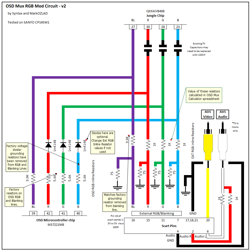
The inline resistance values needed for properly mixing your RGB signal with the OSD RGB signal can be found by cross-referencing the inline resistors on your CRT's OSD circuit with the table below. An example of a typical muxing circuit is also shown below in a seperate image. The diodes on the OSD line are optional but keep in mind you will need different resistance values of diodes are present on the OSD line (see chart).
Basic Universal Requirements
Your jungle chip (also known as the chroma chip or chroma jungle) must have analog RGB inputs. These inputs are generally being used already for the OSD, and if you follow the circuit it will lead you to another IC (called the Micon or Microcomputer) which generates the OSD signals and does other unrelated functions. If you cant find your jungle chip on the schematic, its always the LAST IC to be in the RGB output signal chain before the RGB signals go to the neckboard. Follow the signals backwards from the neckboard using the schematic and you will find the jungle chip.
- If your jungle does not have RGB inputs you cannot use this method.
- If your jungle has digital RGB inputs you cannot use this method. You will have to look up a datasheet for either the jungle chip or the OSD chip to determine if the signal is analog or digital. Some Jungles support both types and can only be switched using the EEPROM which is usually not possible. If you do not have the datasheets you can sometimes tell from looking at the chassis schematics. If you don't see any coupling capacitors or resistors tied to ground in the OSD RGB lines then its likely a digital OSD signal (but I've recently seen some cases where it did still support both - dont let this one stop you). If you feed 5v to the blanking pin and get a solid color screen (white, green, etc) instead of a blank black screen it means its a digital OSD, which is not moddable. Blank screen is only a positive sign to move forward, not a guarantee of compatability.
- If your jungle has RGB inputs which are unused, you can skip muxing entirely and connect your input signals directly to those pins. Make sure to use 75ohm termination resistors on each signal and place a 0.1uF film capacitor in series for each color signal input. There may also be a blanking/input trigger pin you need to feed 5v to activate the RGB input. Check the jungle's datasheet for more information.
List of CRTs which support RGB via Muxing
Partial list:
- American Dynamics HS-CM217A
- Sharp 13H-M60
- Sharp 27K-S100
- Sharp 27N-S300
- Sharp 32C240
- Sharp 13VT-L100
- Sharp 13VT-J100
- Sharp 32UC4
- Sharp 27C530
- Sharp 13J-M100
- Sharp 32C230
- Sharp 27U-S600
- Sharp 25VT-J100
- Sharp 13K-M100
- Sharp 13L-M100B
- Sharp 27F543
- Sharp 27F640
- Sharp 27F640
- Sony KV-27HFR
- Sony KV-13M42
- Sony KV-32XBR51
- Sony KV-24FV12
- Sony KV-27V42
- Sony KV-27EXR95
- Sony KV-16GW1
Credit
The OSD Mux method is courtesy of MarkOZLAD on Shmups Forum.
Circuit Diagram